Introduction
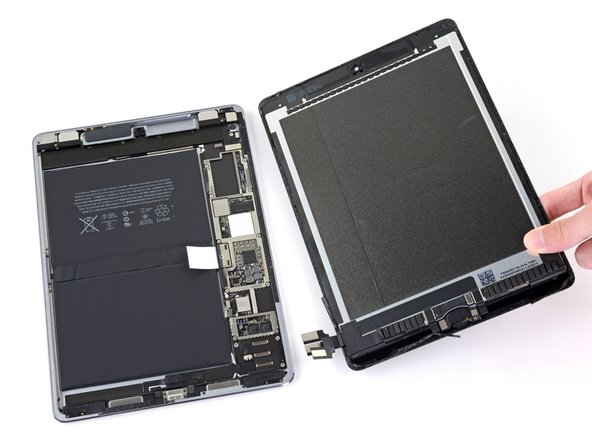
Follow this guide to remove and replace the battery for the iPad Pro 9.7”.
This extensive procedure requires you to remove the logic board in order to free the battery for removal.
This guide is written with a cellular model iPad Pro. If your iPad is not the cellular model, skip the first step.
Because there are steps in this guide where the battery may remain connected to the logic board, leave the iPad on until the battery is completely discharged (the iPad turns itself off) before attempting this guide.
Have plenty of high concentration (over 90%) isopropyl alcohol to help make residue cleanup easier.
If your battery is swollen, take appropriate precautions.
What you need
-
-
Insert a SIM card eject tool, bit, or a paperclip into the small hole in the SIM card tray, located near the bottom edge of the iPad.
-
Press firmly to eject the tray.
-
Remove the SIM tray.
 Ask FixBot
-
-
-
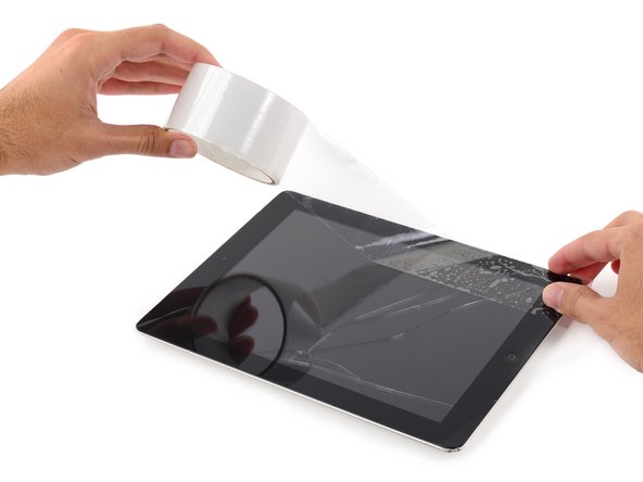
If your display glass is cracked, keep further breakage contained and prevent bodily harm during your repair by taping the glass.
-
Lay overlapping strips of clear packing tape over the iPad's display until the whole face is covered.
-
Do your best to follow the rest of the guide as described. However, once the glass is broken, it will likely continue to crack as you work, and you may need to use a metal prying tool to scoop the glass out.
-
-
-
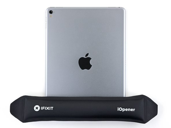
Handling it by the tabs on either end, place a heated iOpener over the top edge of the iPad.
-
Let the iOpener sit on the iPad for two minutes to soften the adhesive securing the front panel to the rest of the iPad.
-
-
-
As you follow the directions, take special care to avoid prying in the following areas:
-
Home Button
-
Front Facing Camera
-
Main Camera
-
-
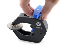
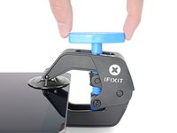
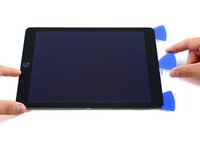
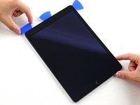
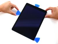
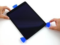
Tool used on this step:Clampy - Anti-Clamp$24.95
-
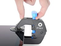
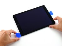
Elevate the iPad enough for the Anti-Clamp's arms to rest above and below the screen.
-
Pull the blue handle towards the hinge to disengage opening mode.
-
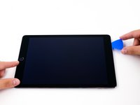
Position the suction cups near the top edge of the iPad—one on the front, and one on the back.
-
Push down on the cups to apply suction to the desired area.
-
-
-
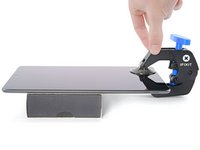
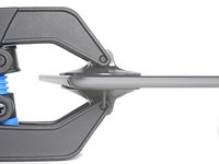
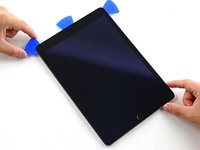
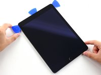
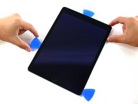
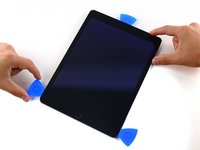
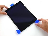
Push the blue handle away from the hinge to engage opening mode.
-
Turn the handle clockwise until you see the cups start to stretch.
-
Wait one minute to give the adhesive a chance to release and present an opening gap.
-
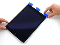
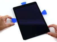
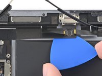
Insert an opening pick under the screen when the Anti-Clamp creates a large enough gap.
-
Skip the next two steps.
-
-
-
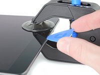
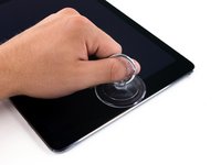
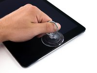
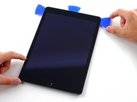
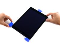
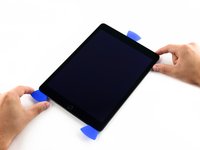
Place a suction cup over the iPad's front-facing camera and press down to create a seal.
-
-
-
Firmly pull up on the suction cup to create a small gap between the front panel and the rear case.
-
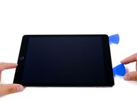
Once you've opened a sufficient gap, insert an opening pick into the gap to prevent the adhesive from resealing.
-
-
-
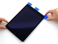
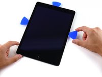
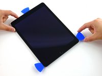
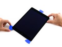
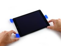
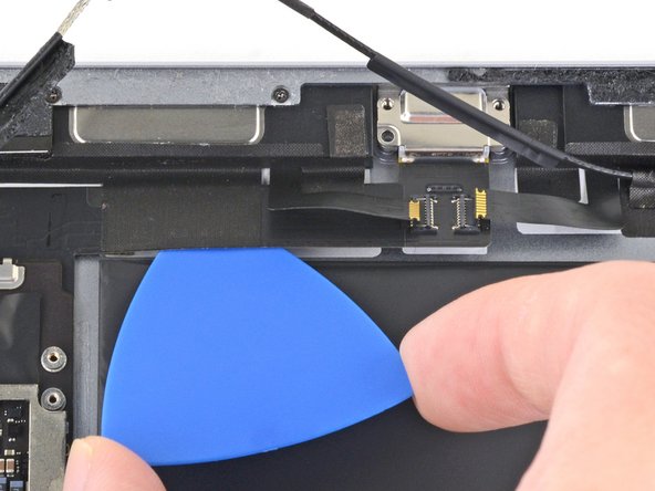
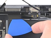
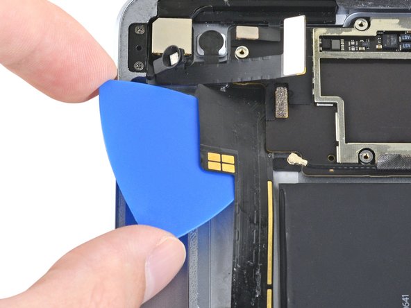
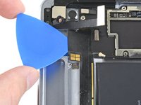
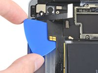
Slide the pick along the edge of the display, towards the headphone jack.
-
If there is still a considerable amount of resistance when sliding the opening pick, repeat the iOpener heating procedure and apply additional heat.
-
-
-
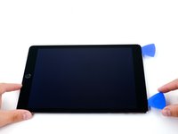
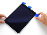
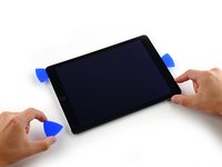
Slide the second pick along the top edge of the iPad, towards the Sleep/Wake Button.
-
-
-
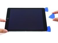
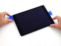
Bring the right opening pick down and around the top right corner of the iPad.
-
-
-
Reheat the iOpener and lay it over the right edge of the display to loosen the adhesive underneath.
-
-
-
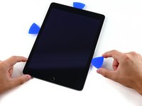
Slide the left-hand opening pick about halfway down the edge of the display.
-
-
-
Slide the opposite opening pick down to the bottom right corner of the iPad.
-
-
-
Slide the left-hand opening pick down the edge of the display until you reach the corner.
-
-
-
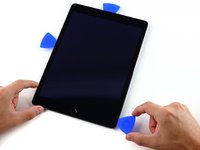
Slide the left-hand opening pick along the bottom edge of the display, then remove it from the bottom right corner of the iPad.
-
-
-
Use picks to ensure most of the adhesive has been cut through on the top, left, and bottom sides.
-
Twist the top and bottom picks to separate the display assembly from the rear case.
-
-
-
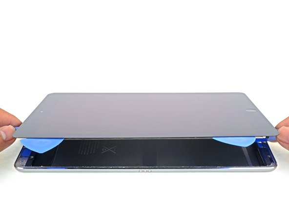
Swing the display assembly towards the right of the case, using the right edge as a hinge.
-
As you move the display assembly, make sure that the display ribbon cable is not being stressed.
-
Continue swinging the display assembly until it lays flat next to the rear case.
-
-
-
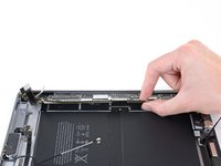
Use a Phillips screwdriver to remove the eleven 1.3 mm screws securing the EMI shield.
-
-
-
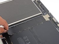
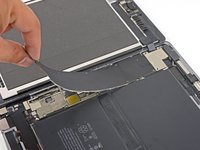
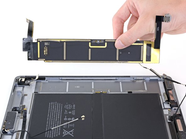
Lift the logic board EMI shield, starting at the edge nearest the top of the iPad.
-
Slowly peel the EMI shield up from the logic board.
-
Remove the logic board EMI shield.
-
-
-
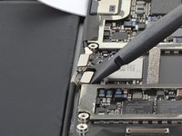
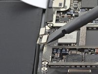
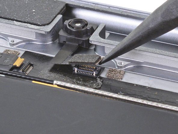
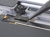
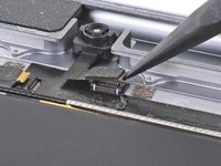
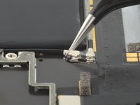
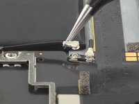
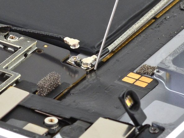
Use a Phillips driver to remove the 1.7 mm-long screw securing the battery connector.
-
-
-
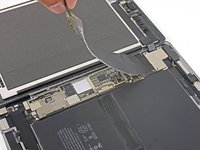
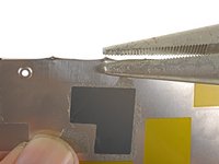
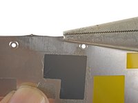
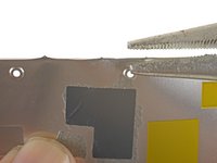
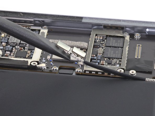
Squeeze the sharp protrusion with a pair of pliers to flatten it.
-
Repeat the process for all sharp protrusions along the edges of the EMI shield.
-
-
-
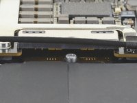
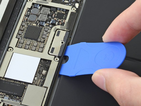
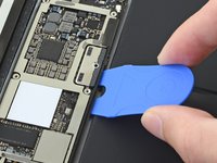
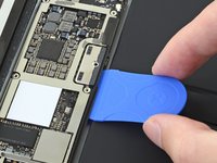
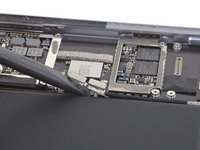
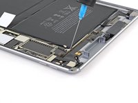
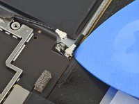
Slide the battery blocker underneath the left side of the logic board's battery connector at a 35 degree angle.
-
Leave the battery blocker in place as you work.
-
-
-
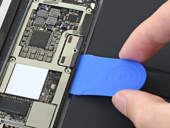
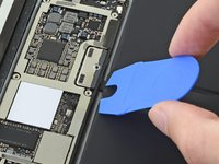
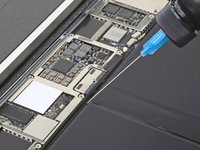
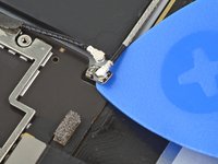
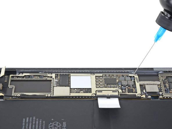
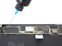
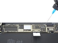
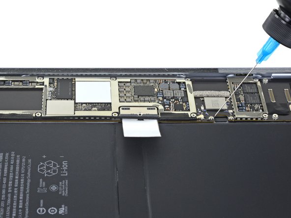
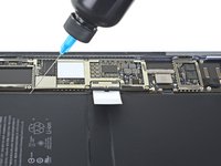
Apply a few drops of high-concentration (90% or higher) isopropyl alcohol under the logic board to the left and right of the battery connection.
-
Wait one minute for the isopropyl alcohol to weaken the adhesive under the logic board.
-
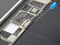
Try to insert the battery blocker. If the logic board doesn't easily lift up, apply a few more drops of isopropyl alcohol.
-
-
-
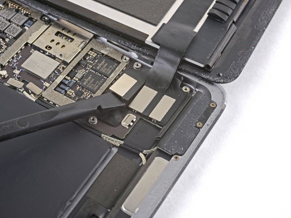
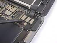
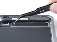
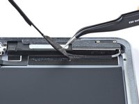
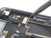
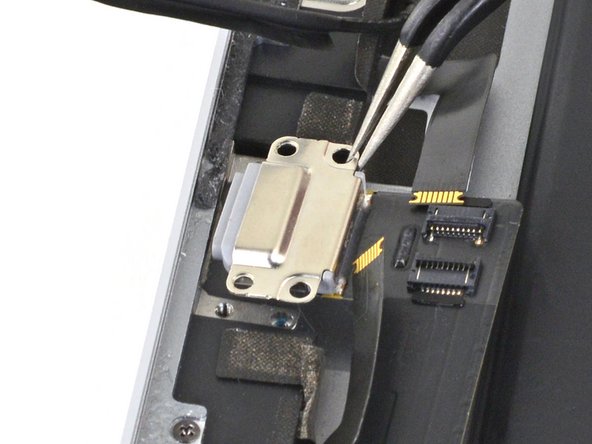
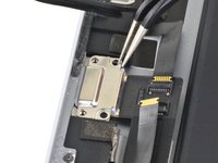
Use a Phillips screwdriver to remove the three 1.3 mm Phillips screws securing the display cable bracket.
-
-
-
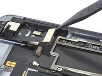
Use the flat end of the spudger to disconnect the display assembly connector from the motherboard socket.
-
-
-
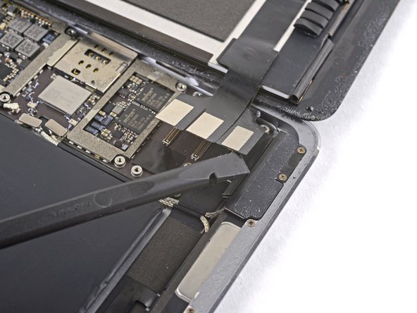
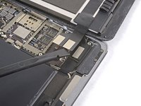
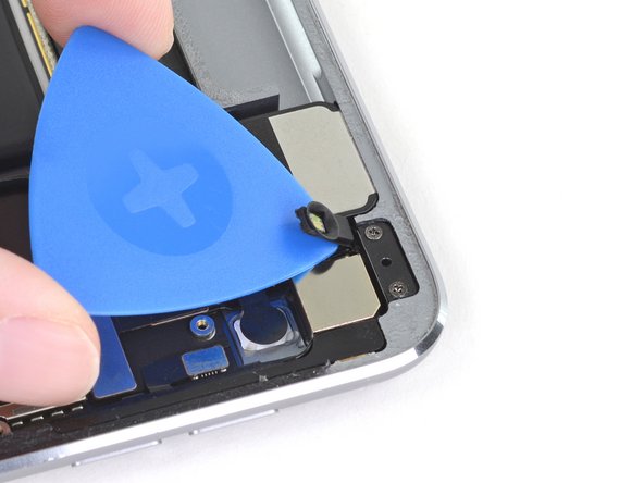
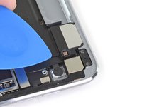
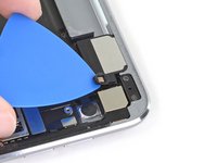
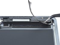
Slide an opening pick under the right ambient light sensor to loosen its adhesive.
-
-
-
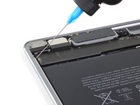
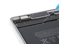
Use a Phillips screwdriver to remove the four 1.9 mm-long screws securing the upper speaker to the frame.
-
-
-
-
Apply a few drops of high-concentration (90% or higher) isopropyl alcohol under the upper speaker.
-
Wait one minute for the isopropyl alcohol to weaken the adhesive under the upper speaker.
-
-
-
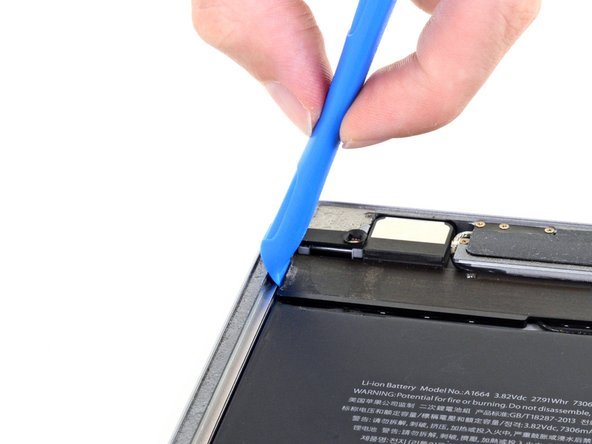
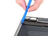
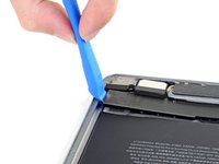
Use an opening tool to pry up the left edge of the upper speaker.
-
-
-
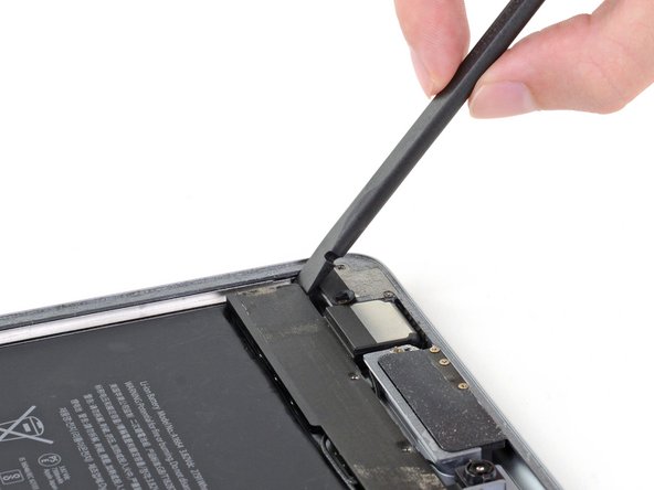
Use the flat end of a spudger to push the left side of the upper speaker toward the battery just enough for the left speaker to slide out of its recess in the frame.
-
-
-
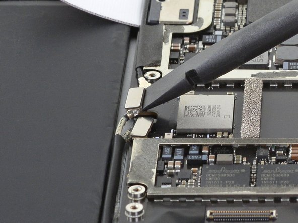
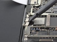
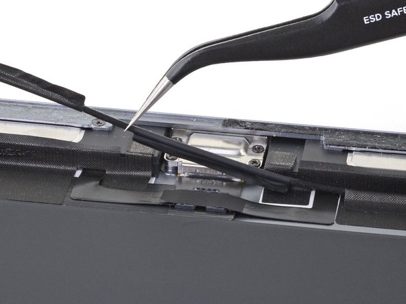
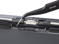
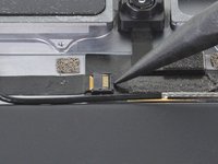
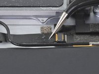
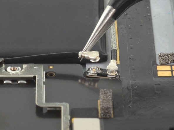
Use the flat end of a spudger to disconnect the right antenna's coaxial connector from its socket.
-
-
-
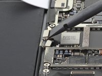
Use the flat end of a spudger to disconnect the left antenna's coaxial connector from its socket.
-
-
-
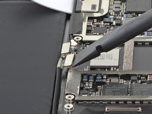
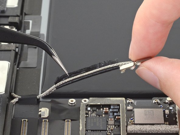
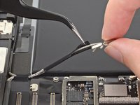
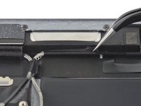
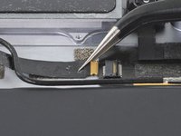
Use the flat end of a spudger to lift the bundled left and right antenna cables away from the frame.
-
-
Tool used on this step:Tweezers$4.99
-
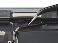
Use a pair of tweezers to remove the adhesive that was securing the bundled antenna cables to the frame.
-
-
-
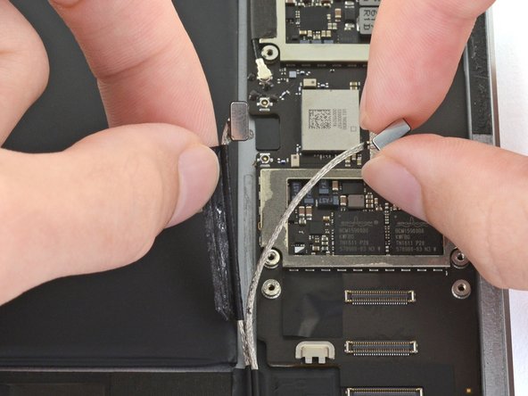
Use a pair of tweezers to peel up the sticker bundling the left and right antenna cables together.
-
-
Tool used on this step:Tweezers$4.99
-
Use a pair of tweezers to lift up the small sticker near the lower right speaker securing the right antenna to the frame.
-
-
-
Use the pointed end of a spudger to detach the foam spacer adhered to the second right antenna sticker.
-
-
-
Remove the foam spacer from the second right antenna sticker.
-
-
-
Use a pair of tweezers to detach the large right antenna sticker between the logic board and the antenna.
-
-
Tool used on this step:Tweezers$4.99
-
Use a pair of tweezers to lift up the small sticker next to the lower right speaker securing the left antenna cable to the frame.
-
-
-
Use a pair of tweezers to detach the large left antenna cable sticker near the lower right speaker.
-
-
-
Use a pair of tweezers to lift the left antenna and its third sticker away from the Lightning port area of the frame.
-
-
-
Use the pointed end of a spudger to detach the foam spacer adhered to the fourth left antenna cable sticker.
-
-
-
Remove the foam spacer from the fourth left antenna cable sticker.
-
-
Tool used on this step:Tweezers$4.99
-
Use a pair of tweezers to remove the sticker covering the left ambient light sensor's ZIF connector.
-
-
-
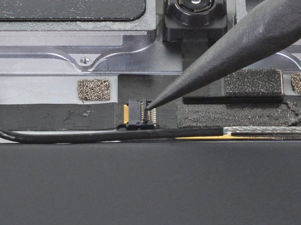
Use the pointed end of a spudger to flip up the locking flap on the left ambient light sensor's ZIF connector.
-
-
-
Use a pair of tweezers to grip the left ambient light sensor ribbon cable as close as possible to its contacts.
-
Pull the ribbon cable out of the ZIF connector.
-
-
-
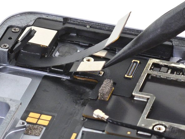
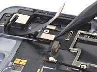
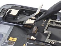
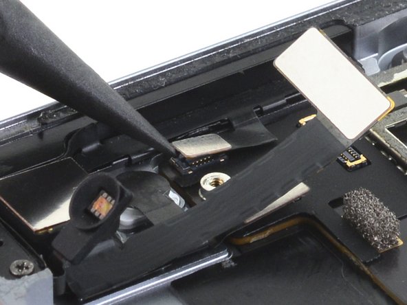
Use the pointed end of a spudger to disconnect the front camera's press connector from its socket.
-
-
-
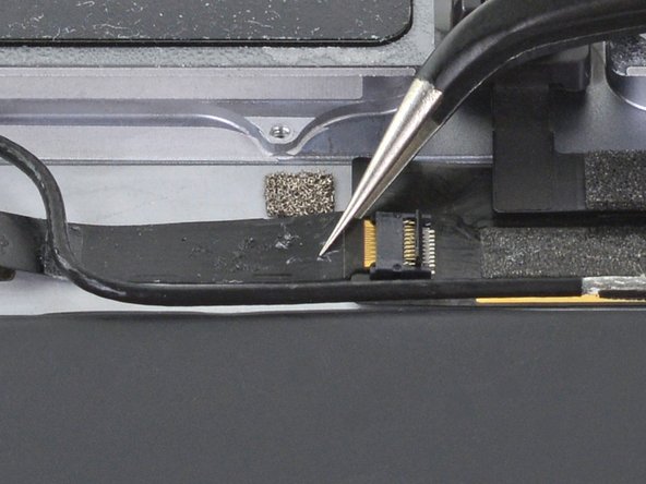
Use a pair of tweezers to grip the bottom coaxial connector on the top interconnect board by its metal frame.
-
Lift straight up to disconnect the coaxial connector from the interconnect board.
-
-
-
Apply a few drops of high-concentration (90% or higher) isopropyl alcohol to the edges of the top interconnect board.
-
Wait thirty seconds for the isopropyl alcohol to weaken the adhesive under the top interconnect board.
-
-
-
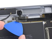
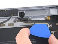
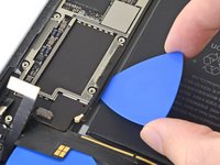
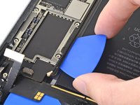
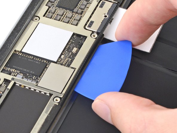
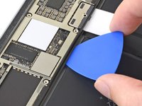
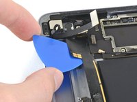
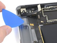
Use an opening pick to cut through the adhesive under the top interconnect board and detach it from the frame.
-
-
-
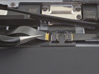
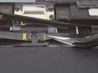
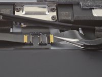
Use the pointed end of a spudger to disconnect the rear camera's press connector from its socket.
-
-
-
Use the pointed end of a spudger to disconnect the power button assembly's press connector from its socket.
-
-
-
Use the pointed end of a spudger to disconnect the volume buttons' press connector from its socket.
-
-
-
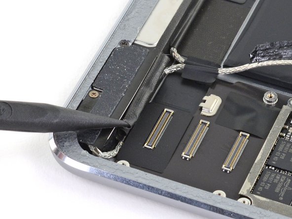
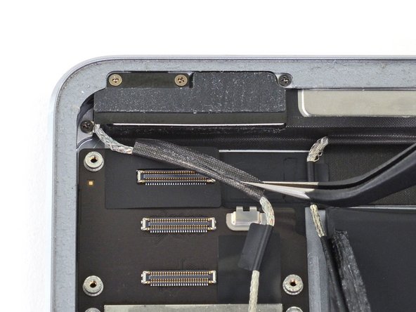
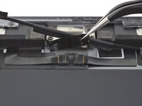
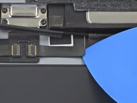
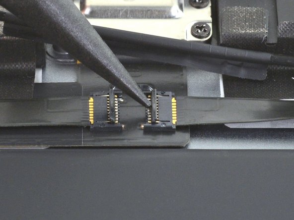
Use a pair of tweezers to remove the sticker covering the ZIF connectors near the Lightning port.
-
-
-
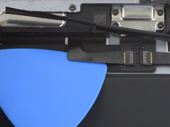
Use an opening pick to cut through the adhesive under the right ribbon cable next to the lower speaker (Lightning port oriented up) and detach it from the frame.
-
-
-
Use an opening pick to cut through the adhesive under the left ribbon cable next to the lower speaker and detach it from the frame.
-
-
-
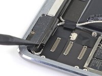
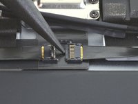
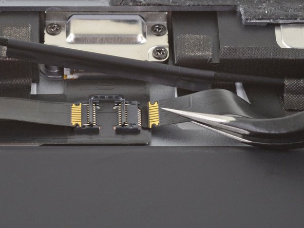
Use the pointed end of a spudger to flip up the hinged locking flap on the left ribbon cable ZIF connector.
-
-
-
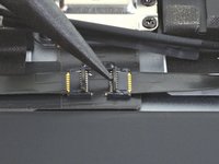
Use the pointed end of a spudger to flip up the hinged locking flap on the right ribbon cable ZIF connector.
-
-
-
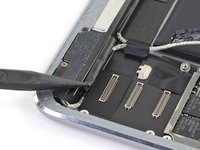
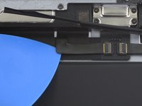
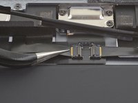
Use a pair of tweezers to grip the left ribbon cable as close as possible to its contacts and pull the ribbon cable out of the ZIF connector.
-
-
-
Use a pair of tweezers to grip the right ribbon cable as close as possible to its contacts and pull the ribbon cable out of the ZIF connector.
-
-
-
Remove the four Phillips screws securing the Lightning port:
-
Two 2.5 mm screws
-
Two 1.5 mm screws
-
-
-
Strips of adhesive secure the logic board to the frame. In the next steps, you'll weaken and cut through the adhesive to detach the logic board from the frame.
-
-
-
Carefully turn the iPad over.
-
Heat an iOpener and apply it to the top, left, and bottom edges of the rear case for one minute on each edge.
-
-
-
Use an opening pick to cut through the adhesive under the Lightning port ribbon cable to detach it from the frame.
-
-
-
Use a pair of tweezers to lift up the smaller sticker to the left of the Lightning port (when the Lightning port is oriented up).
-
-
-
Use a pair of tweezers to lift up the larger sticker to the left of the Lightning port.
-
-
-
Use a pair of tweezers to grip the Lightning port by the bottom right screw hole.
-
Pull the Lightning port out of its recess.
-
-
-
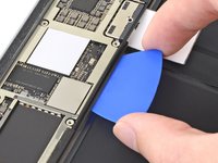
Apply a few drops of high-concentration isopropyl alcohol under the left edge of the upper logic board arm (Lightning port oriented down).
-
Wait thirty seconds for the isopropyl alcohol to weaken the adhesive under the upper logic board arm.
-
-
-
Use an opening pick to cut through the adhesive under the upper logic board arm and detach it from the frame.
-
-
-
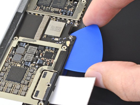
Insert an opening pick about 0.5 inches (13 mm) under the top edge of the larger portion of the upper logic board arm.
-
Leave the opening pick under the upper logic board arm to prevent it from re-adhering to the frame.
-
-
-
Apply a few drops of high-concentration isopropyl alcohol to the right edge of the logic board.
-
-
-
Apply a few drops of high-concentration isopropyl alcohol to the left edge of the logic board.
-
Wait one minute for the isopropyl alcohol to weaken the adhesive under the logic board.
-
-
-
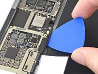
Slide an opening pick about 0.5 inches (13 mm) under the top of the logic board's left side to cut through the adhesive.
-
Remove the opening pick.
-
-
-
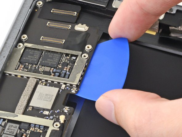
Slide the opening pick about 0.5 inches (13 mm) under the logic board's left side next to the battery connector.
-
Remove the opening pick.
-
-
-
Slide the opening pick about 0.5 inches (13 mm) under the logic board on the other side of the battery connector.
-
Remove the opening pick.
-
-
-
Slide the opening pick about 0.5 inches (13 mm) under the bottom of the logic board's left side.
-
Remove the opening pick.
-
-
-
Remove the opening pick from the upper logic board arm.
-
-
Tool used on this step:Tweezers$4.99
-
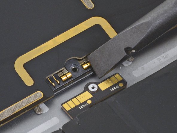
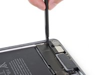
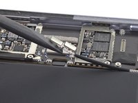
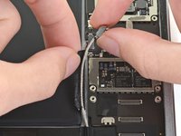
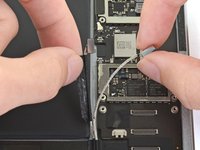
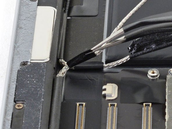
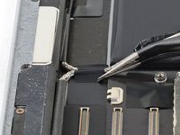
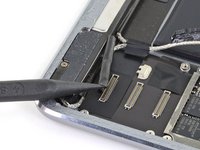
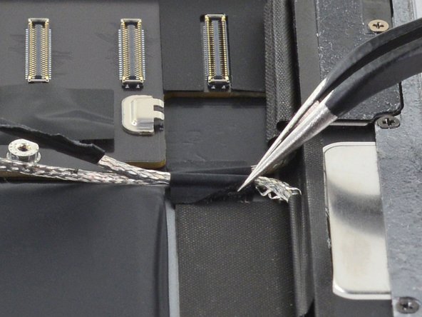
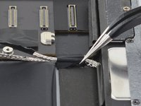
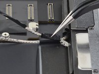
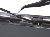
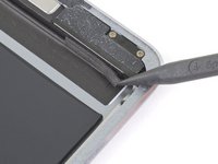
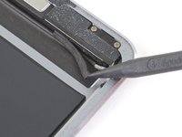
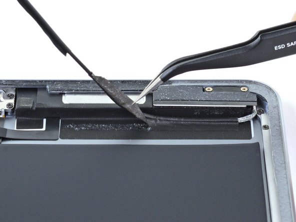
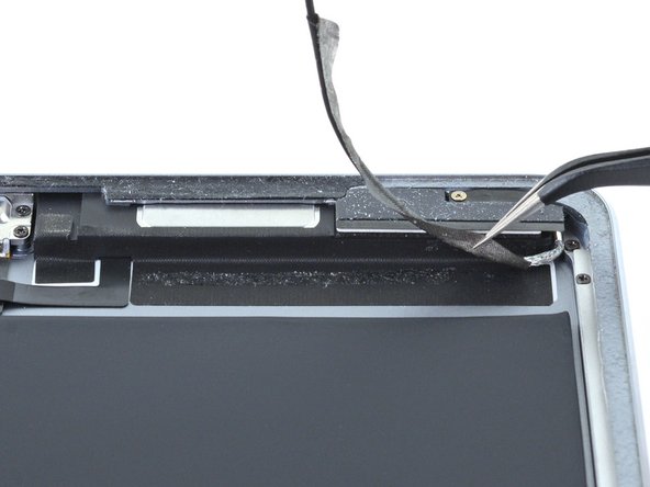
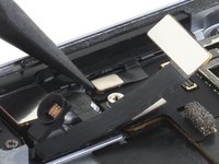
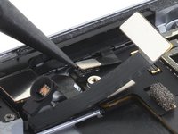
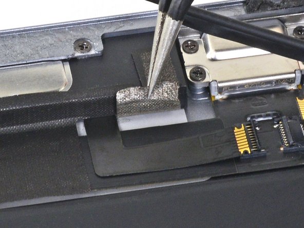
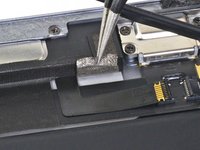
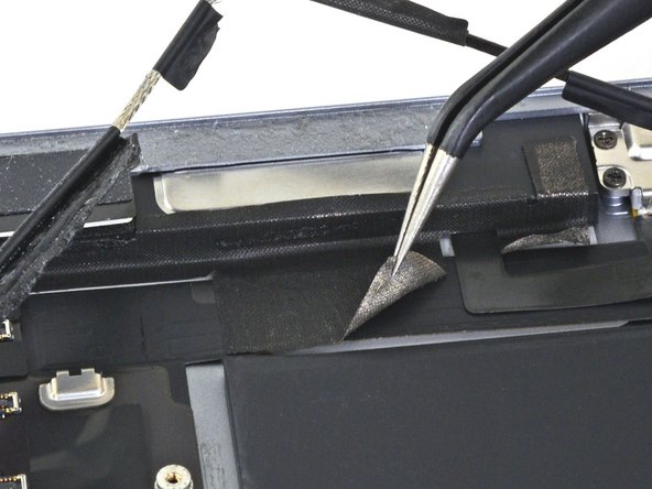
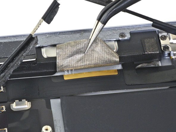
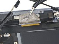
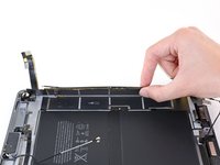
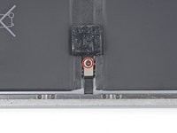
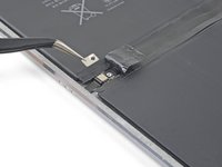
Use tweezers to gently lift the end of the black tape covering the mid-battery circuit board nearest the Smart Connector.
-
-
-
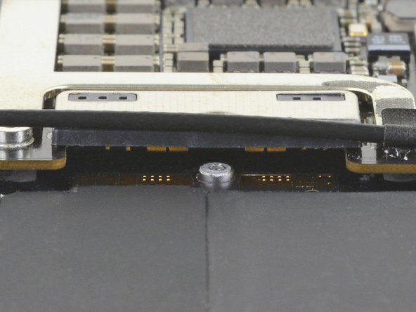
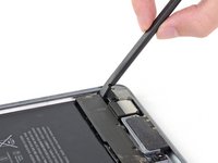
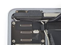
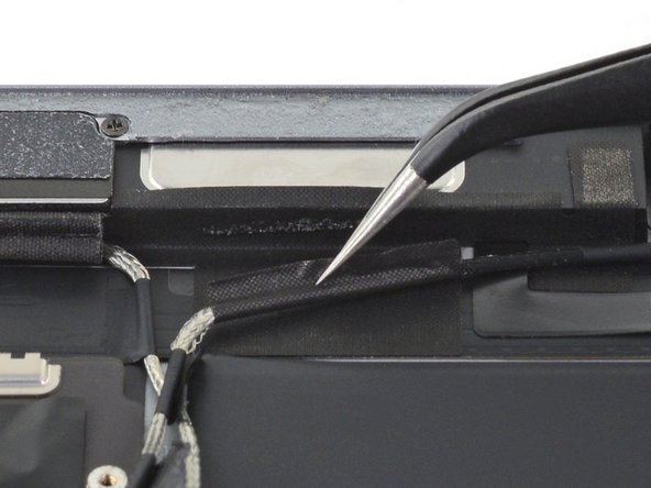
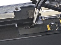
Remove the 1.7 mm Phillips screw holding the Smart Connector cable cover in place.
-
Remove the Smart Connector cable cover.
-
-
-
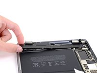
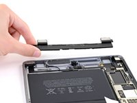
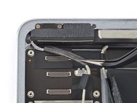
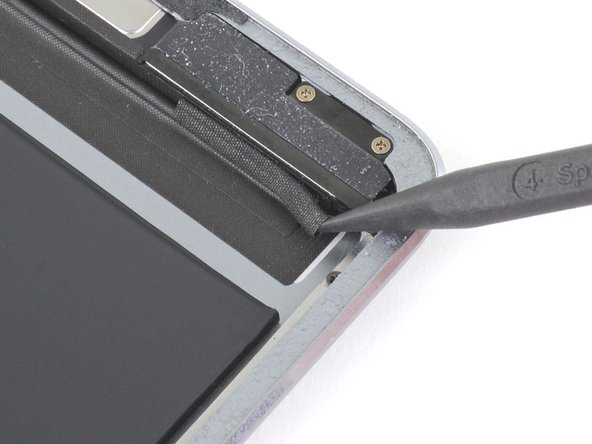
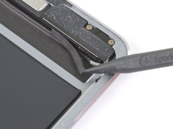
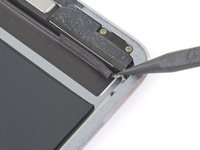
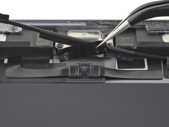
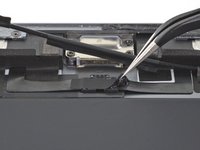
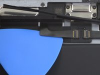
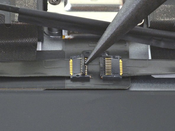
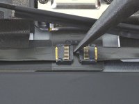
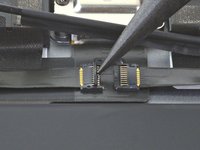
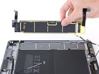
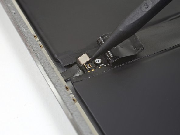
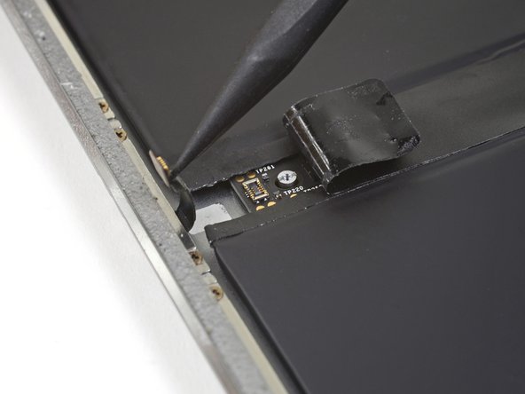
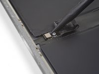
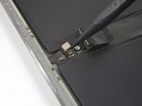
Use the point of a spudger to pry up and disconnect the Smart Connector from its socket between the battery cells.
-
Push the Smart Connector flex cable up and out of the way.
-
-
-
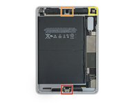
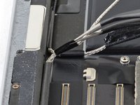
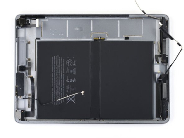
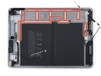
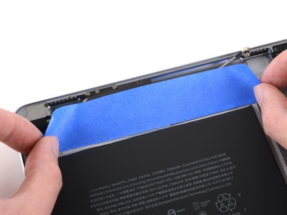
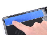
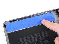
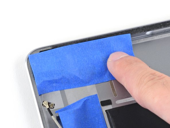
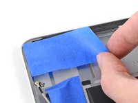
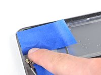
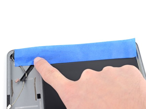
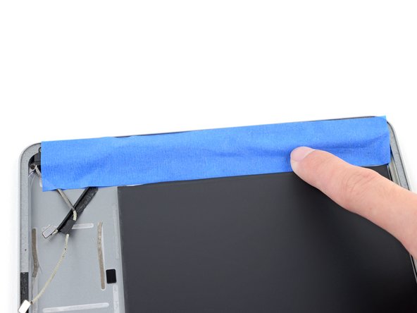
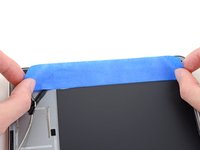
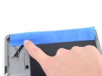
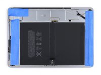
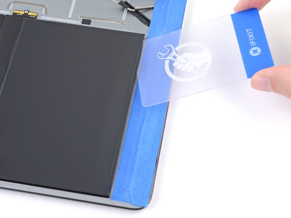
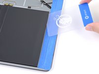
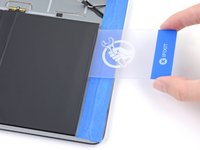
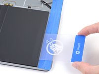
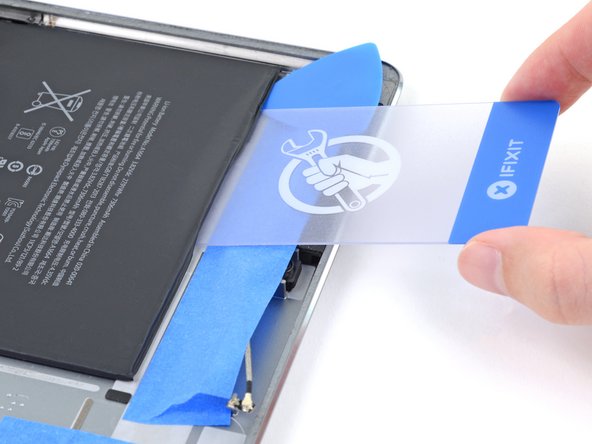
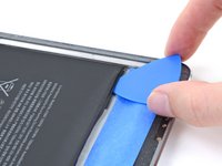
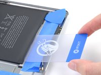
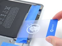
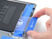
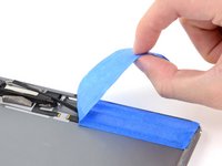
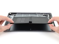
Apply a piece of masking or painter's tape to the upper components. The edge of the tape should be close to, but not touching, the battery.
-
Press down on the tape so that it adheres firmly to the frame and components.
-
-
-
Once complete, the masking should look like the first image.
-
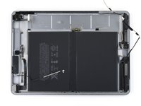
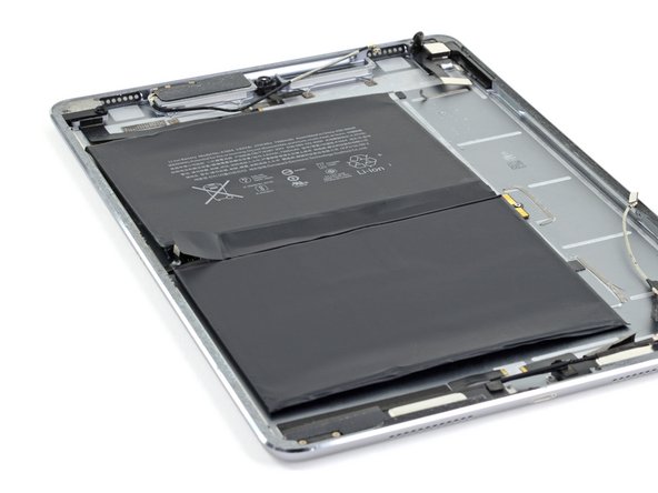
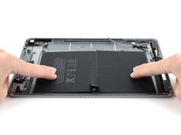
Four strips of strong adhesive hold the battery in place.
-
-
-
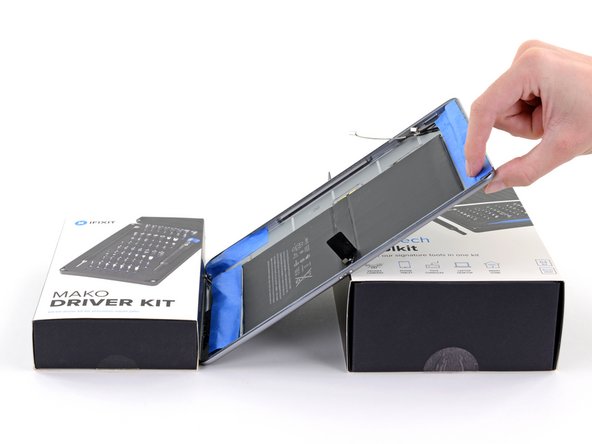
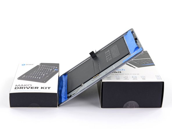
Prepare a work area where the iPad can rest in a tilted position, to allow adhesive remover to trickle down to the adhesive strips.
-
-
-
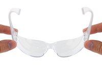
Wear eye protection when handling and applying the adhesive remover. (Eye protection is included in your kit.)
-
Do not wear contact lenses without eye protection.
-
-
-
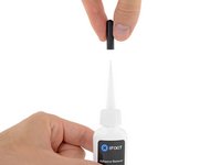
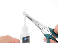
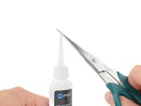
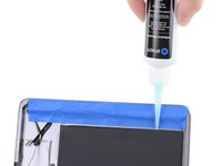
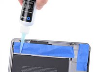
Pull off the black rubber stopper from your bottle of adhesive remover.
-
Use scissors to cut off the sealed tip of the applicator.
-
-
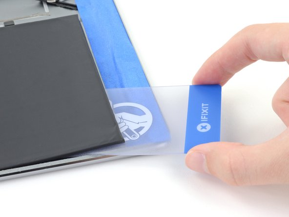
Tool used on this step:Plastic Cards$2.99
-
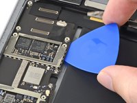
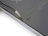
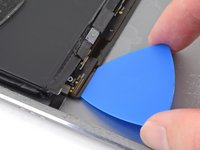
Carefully insert a plastic card under the bottom right corner of the battery.
-
Slowly slide the plastic card across the bottom edge of the battery to make a gap for the liquid adhesive remover.
-
-
-
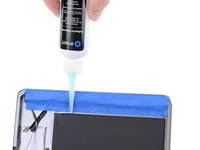
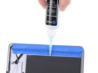
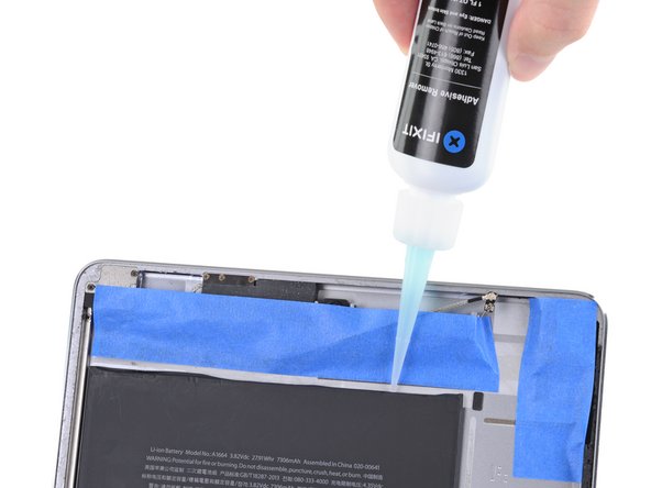
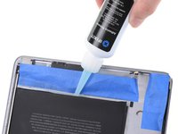
Tilt the bottom of the iPad up.
-
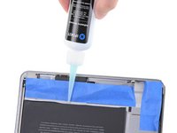
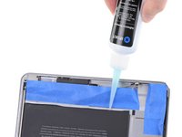
Apply a few drops of adhesive remover evenly along the elevated edge of the battery.
-
-
-
Rest the iPad in a slanted position, bottom edge up, and wait 2-3 minutes to allow the adhesive remover to penetrate and soften the first adhesive strip.
-
-
-
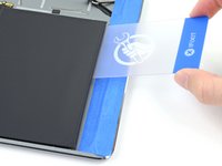
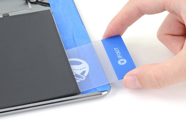
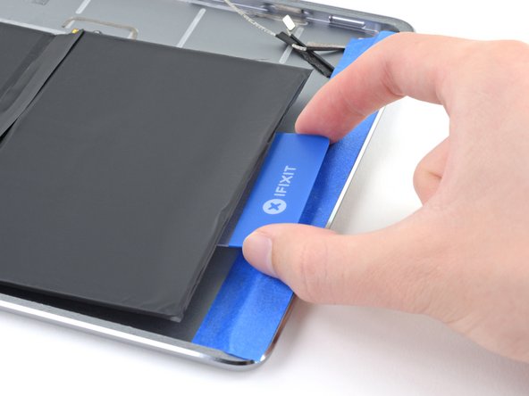
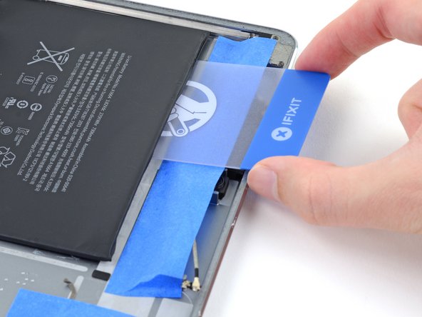
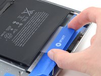
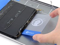
Slide a plastic card into the bottom edge of the battery.
-
Push the card in slowly and firmly. Gently wiggle and twist the card to help it slice through the adhesive.
-
-
-
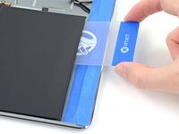
You can also approach the adhesive strip with the plastic card from battery's other bottom corner.
-
Continue slicing until you have separated the battery from the first adhesive strip.
-
-
-
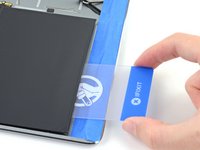
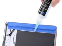
Tilt the bottom of the iPad up.
-
Reapply adhesive remover into the gap for the second adhesive strip, located deeper underneath the bottom battery cell.
-
Repeat the application, waiting, and slicing process until the second adhesive strip is separated from the battery.
-
-
-
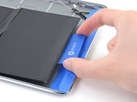
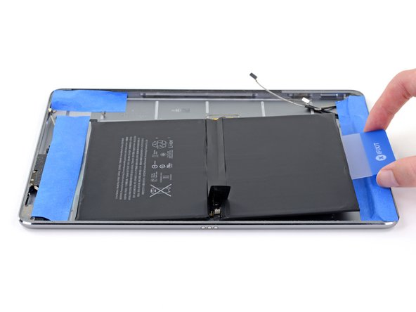
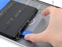
Slide an opening pick under the top edge of the battery, creating a gap large enough for a plastic card.
-
Insert a plastic card under the top edge and slide it across the entire length, creating a gap for the adhesive remover.
-
-
-
Apply adhesive remover into the gap to help weaken the third adhesive strip.
-
-
-
Rest the iPad in a slanted position, top edge up, for 2-3 minutes to allow the adhesive remover to weaken the third strip.
-
-
-
Use a plastic card to slice through the third adhesive strip.
-
-
-
Repeat the application, waiting, and slicing process to release the last adhesive strip located deeper underneath the top battery cell.
-
-
-
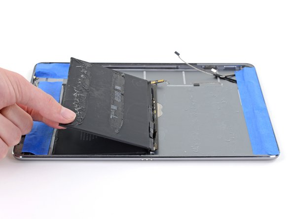
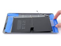
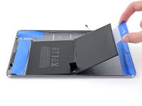
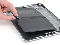
Use the plastic card or your fingers to flip the bottom half of the battery over so that it rests on top of the upper half.
-
-
-
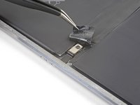
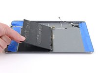
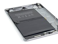
Slide an opening pick underneath the mid-battery circuit board, near the Smart Connector.
-
Carefully slice underneath the board around the post to release the board from the rear case.
-
-
-
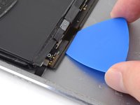
Slide the long edge of a plastic card about 0.5 inches (13 mm) under the center of the mid-battery circuit board to cut through the remaining adhesive.
-
-
-
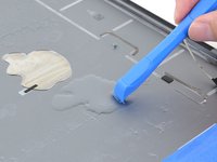
Thoroughly clean the back case of all adhesive residue.
-
Apply adhesive remover or high concentration (over 90%) isopropyl alcohol to the residue.
-
Use an opening tool to scrape and loosen the residue.
-
Be sure to wipe the residue away in one direction to prevent smearing.
-
You can remove the masking tape as well as any protective gear once you are done cleaning.
-
-
-
Place the replacement battery pack so that the two screw posts line up with their holes on the mid-battery circuit board and battery connector.
-
-
-
Lift the bottom edge of the battery up slightly.
-
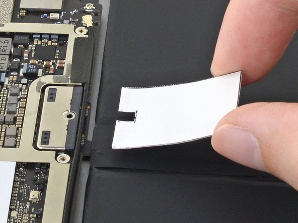
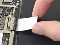
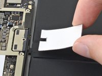
Use tweezers or your fingers to peel the single clear plastic covering off of the entire bottom side of the battery.
-
Align the battery such that it falls in place with the screw post near the Smart Connector.
-
Gently lay the battery down into its recess and press it firmly into place.
-


To reassemble your device, follow these instructions in reverse order.
Take your e-waste to an R2 or e-Stewards certified recycler.
Repair didn’t go as planned? Check out our iPad Pro 9.7” Answers Community for troubleshooting help.
Cancel: I did not complete this guide.
42 other people completed this guide.

18 Guide Comments
That’s an excellent guide! I had to replace both the battery and the display. The iPad seems fixed and boots but shuts down after 3min/180s due to "no successful checkins from com.apple.thermalmonitord since wake". The other services listed in the dump all report successful checkins. I have no idea whether that rather indicates something went wrong with the battery replacement or with the display exchange (and associated home button transfer). A hard DFU didn’t help.
Did you ever get this fixed? I’m running into the same thing.
Hello, I tap the home button, Apple is very picky about the exchange. Just try the original home button if it is still available.
Used this guide it is missing the part where you need to remove the screw from the battery post. Post needs to be reissued. I have now tried 3 OEM batteries including reinstalling the existing one and all cause the iPad to go into a restart loop I think iOS 14 devices are firmware locked as all show 100mAh on Coconut Plus which probably causes the restart loops. Even completed hard reset and total factory reset however still stuck in restart loop
Did you manage to fix this? I got the same result.