Introduction
Follow this guide to remove and replace the logic board for the iPhone SE 2020.
Note: Each iPhone's logic board and Touch ID fingerprint sensor are paired at the factory, so replacing the logic board will disable Touch ID unless you also install a replacement home button that has been properly paired to your new logic board.
What you need
-
-
Remove the two 3.5 mm pentalobe screws on the bottom edge of the iPhone.
-
-
-
Measure 3 mm from the tip and mark the opening pick with a permanent marker.
-
-
Tool used on this step:Clampy - Anti-Clamp$24.95
-
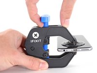
Pull the blue handle backwards to unlock the Anti-Clamp's arms.
-
Slide the arms over either the left or right edge of your iPhone.
-
Position the suction cups near the bottom edge of the iPhone just above the home button—one on the front, and one on the back.
-
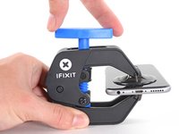
Squeeze the cups together to apply suction to the desired area.
-
-
-
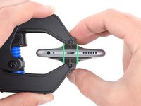
Heat an iOpener and thread it through the arms of the Anti-Clamp.
-
Fold the iOpener so it lays on the bottom edge of the iPhone.
-
Wait one minute to give the adhesive a chance to release and present an opening gap.
-
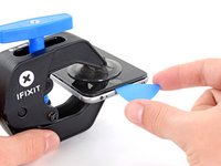
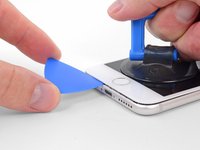
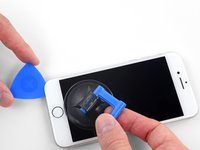
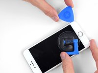
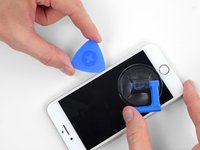
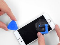
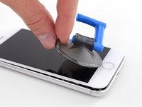
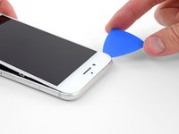
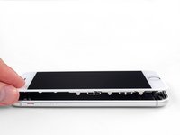
Insert an opening pick into the gap.
-
Skip the next three steps.
-
-
-
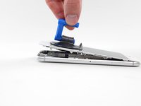
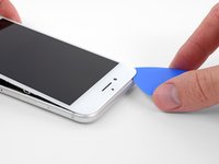
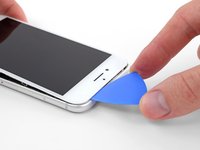
Heating the lower edge of the iPhone will help soften the adhesive securing the display, making it easier to open.
-
Use a hairdryer or prepare an iOpener and apply it to the lower edge of the phone for about 90 seconds in order to soften up the adhesive underneath.
-
-
-
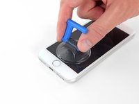
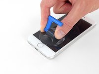
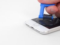
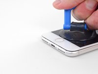
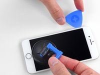
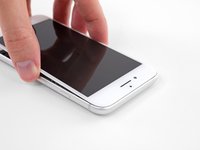
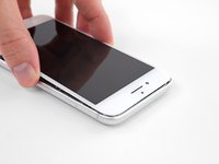
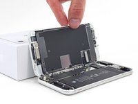
Apply a suction cup to the lower half of the front panel, just above the home button.
-
-
-
Tool used on this step:Magnetic Project Mat$16.96
-
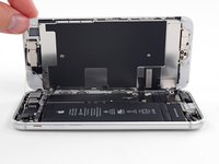
Remove four Phillips screws securing the lower display cable bracket to the logic board, of the following lengths:
-
Two 1.3 mm screws
-
Two 2.8 mm screws
-
Remove the bracket.
-
-
-
Use the point of a spudger to pry the lower display connector out of its socket.
-
-
-
Insert a SIM card eject tool, bit, or a straightened paperclip into the small hole in the SIM card tray.
-
Press to eject the tray.
-
-
-
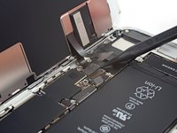
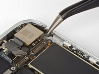
Use the flat end of a spudger to disconnect the camera cable connector by prying it straight up from its socket.
-
-
-
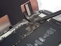
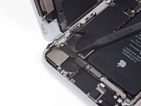
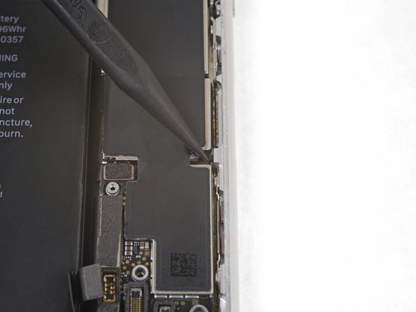
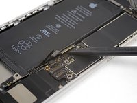
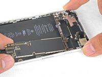
Remove the three Phillips 1.3 mm screws securing the top left antenna component.
-
-
-
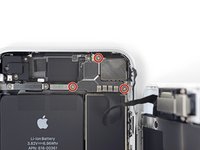
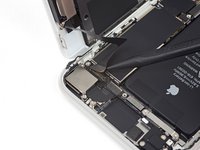
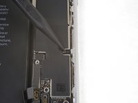
Remove the two Phillips screws securing the grounding clip at the top left edge of the logic board:
-
One 1.5 mm Phillips screw
-
One 2.6 mm Phillips screw
-
-
-
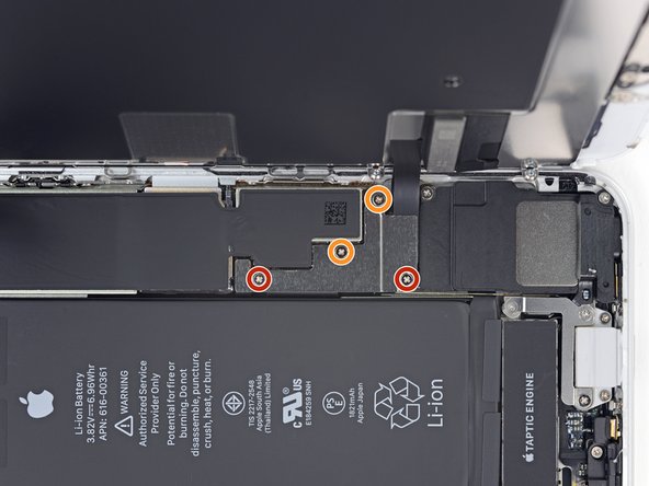
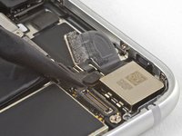
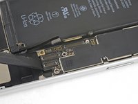
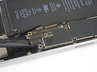
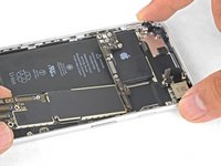
Remove the three screws securing the motherboard:
-
One 1.8 mm Phillips screw
-
One 2.5 mm standoff screw
-
One 2.2 mm standoff screw
-
-
-
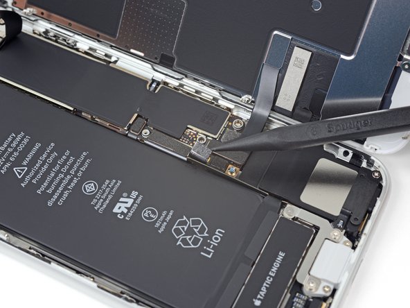
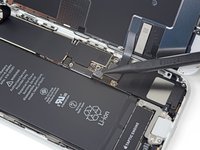
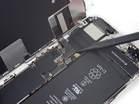
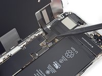
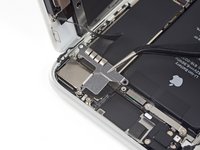
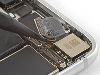
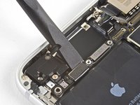
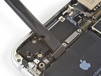
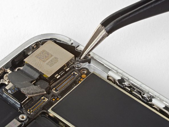
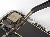
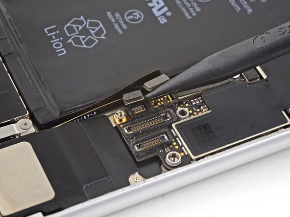
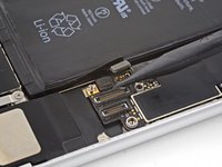
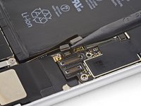
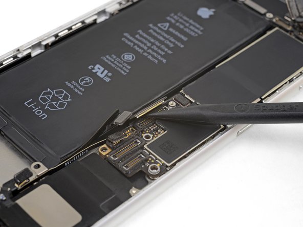
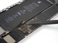
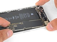
Use the point of a spudger to pry up and disconnect the Wi-Fi diversity antenna cable.
-


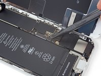


To reassemble your device, follow the above steps in reverse order.
Take your e-waste to an R2 or e-Stewards certified recycler.
Repair didn’t go as planned? Check out our Answers community for troubleshooting help.
Cancel: I did not complete this guide.
31 other people completed this guide.

6 Guide Comments
Where can you buy a logic board
Note: Each iPhone's logic board and Touch ID fingerprint sensor are paired at the factory, so replacing the logic board will disable Touch ID unless you also install a replacement home button that has been properly paired to your new logic board.
So, where can I get a logic board that has been paired with the home button? Or does the pairing happen as part of the install?
Please can you show me where the back lights ic is located