Introduction
If you’re having trouble with Wi-Fi connectivity, try replacing this part. The primary Wi-Fi antenna is integrated into the iPhone’s frame, while the diversity antenna is adhered to the speaker.
What you need
-
-
Power off your iPhone before beginning disassembly.
-
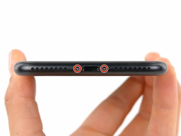
Remove the two 3.4 mm pentalobe screws at the bottom edge of the iPhone.
-
-
-
Use a hairdryer or prepare an iOpener and apply it to the lower edge of the iPhone for about a minute in order to soften up the adhesive underneath.
-
-
-
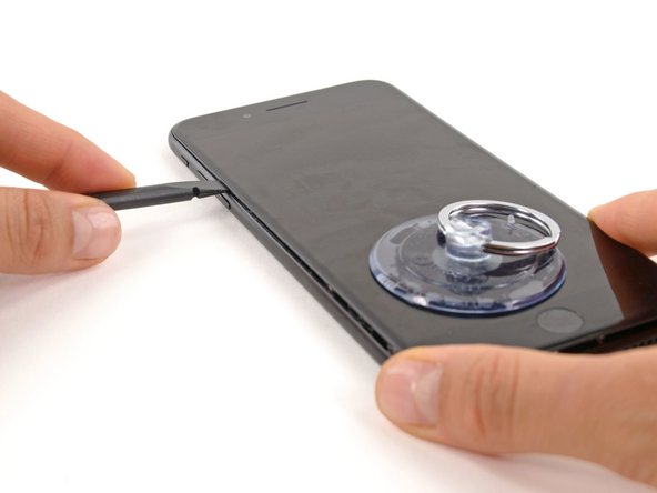
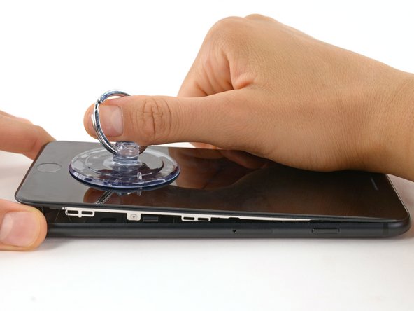
Pull up on the suction cup with firm, constant pressure to create a slight gap between the front panel and rear case.
-
Insert the flat end of a spudger into the gap.
-
While pulling up on the suction cup, twist the spudger to widen the opening between the screen and rear case.
-
-
-
Insert the flat end of the spudger between the front panel and the rear case at the lower left edge of the iPhone.
-
Slide the spudger up the left edge of the phone starting at the lower edge and moving towards the volume control buttons and silent switch, breaking up the adhesive holding the display in place.
-
-
-
Remove the spudger from the left side of the phone and insert the flat end into the bottom right corner.
-
Slide the spudger up the right edge of the phone to the top corner, breaking up the adhesive holding the display in place.
-
-
-
-
Slide an opening pick underneath the display along the top edge of the phone to loosen the last of the adhesive.
-
-
-
Pull the display assembly slightly away from the top edge of the phone to disengage the clips holding it to the rear case.
-
Open the iPhone by swinging the display up from the left side, like the back cover of a book.
-
-
-
Remove the following four tri-point Y000 screws securing the lower display cable bracket to the logic board:
-
Three 1.2 mm screws
-
One 2.6 mm screw
-
-
-
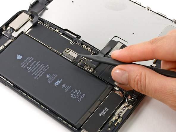
Use the point of a spudger to lift the battery connector out of its socket on the logic board.
-
-
-
Use the flat end of a spudger or a fingernail to disconnect the two lower display connectors by prying them straight up from their sockets on the logic board.
-
-
-
Remove the three tri-point Y000 screws securing the bracket over the front panel sensor assembly connector:
-
One 1.3 mm screw
-
Two 1.0 mm screws
-
Remove the bracket.
-
-
-
Warm the lower speaker area where the antenna is adhered with an iOpener, hair dryer, or heat gun, until it's slightly too hot to touch.
-
-
-
Slide an opening pick between the antenna and the speaker on the right side, and carefully separate the adhesive underneath.
-
-
-
Rotate the speaker and re-insert your opening pick on the opposite side.
-
Separate any remaining adhesive securing the antenna.
-
If necessary, re-heat the adhesive until it separates easily.
-