This guide has more recent changes. Switch to the latest unverified version.
Introduction
Follow this guide to replace the FSC board (aka sub board, daughterboard, or touchpad board) in your Steam Controller (2nd Gen, 2026).
The FSC board connects the touchpads to the main board. Issues with the FSC board could lead to problems with the touchpads. If you need to replace the touchpads themselves, follow this guide to replace the left touchpad, or this guide for the right.
What you need
-
-
Unplug all cables and accessories from the controller, including the Steam Controller Puck.
-
-
Tool used on this step:TR6 Torx Security Screwdriver$5.99
-
Use a T6 Torx screwdriver to remove the seven screws securing the back cover.
-
Throughout this repair, keep track of each screw and make sure it goes back exactly where it came from.
-
-
-
Use a T6 Torx screwdriver to remove the four 7.4 mm‑long screws securing the battery mounting bracket.
-
-
-
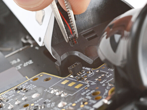
Firmly grip the short edges of one rumble motor connector with a pair of tweezers and pull straight up to disconnect it
-
-
-
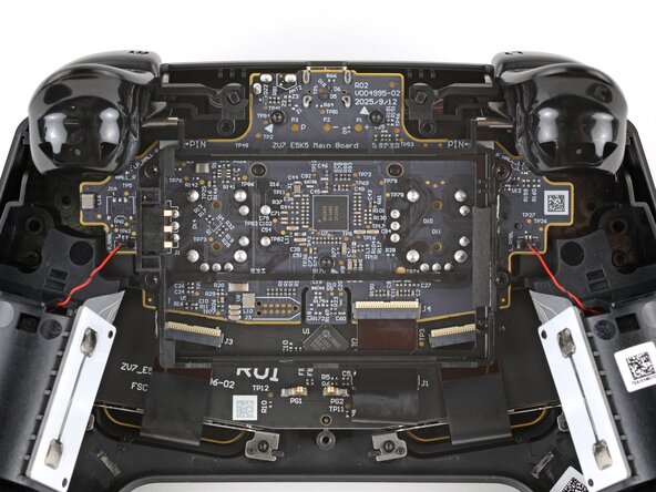
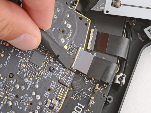
Use a spudger to lift the hinged locking flap on the interconnect cable ZIF connector, located on the bottom edge of the main board.
-
-
-
-
Use a T6 Torx screwdriver to remove the three 7.4 mm‑long screws securing the main board.
-
-
-
Pull the main board down so the top corners clear the triggers.
-
Remove the main board, guiding the joysticks through their cutouts.
-
-
-
If the rubber piece is out of place, remove it and set it aside.
-
-
-
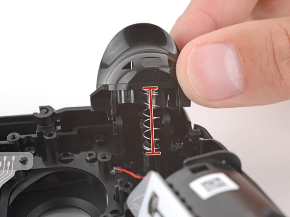
With one hand, fully depress one trigger.
-
With your free hand, use tweezers to pull the hinge pin straight out and remove it.
-
-
-
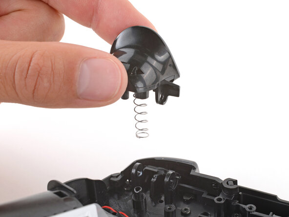
Lift the trigger straight up and remove it.
-
Remove the spring and store it in a safe place for reassembly.
-
-
-
Place one of the trigger springs over its post on the controller.
-
Put the trigger in place, making sure the spring goes over both of its posts (one on the controller and one on the trigger) and that the hinge holes are all aligned.
-
Hold the trigger down and slide the pin through both hinge holes—the pin will stop sliding once it's fully inserted.
-
Test the trigger to ensure the pin was properly installed.
-
Repeat to install the other trigger.
-
-
-
Use a T6 Torx screwdriver to remove the eleven 7.4 mm‑long screws securing the midframe.
-
-
-
Lift the midframe straight up and remove it.
-
If you removed the buttons and their membranes, reinstall them now.
-
Check the two large silicone button membranes and make sure they're aligned properly—if they aren't, button presses may feel off or not register.
-
Use the alignment posts to ensure the midframe is in the right position.
-
-
-
Check if the Steam button's silicone membrane stuck to the button circuit on the midframe.
-
If it did, either put the membrane back in place or set it aside.
-
-
-
Use the flat end of a spudger to lift the hinged, locking flap on one of the touchpad ZIF connectors.
-
-
-
Use a T4 Torx screwdriver to remove the four 6.0 mm‑long screws securing the FSC board.
-
-
-
Remove the FSC board.
-
Use the alignment pegs to ensure the board is correctly positioned.
-
-
-
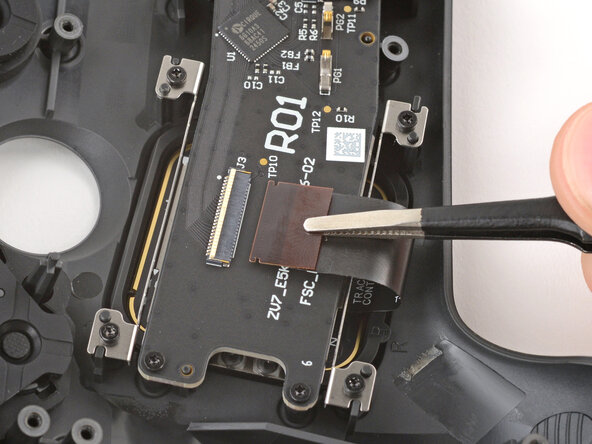
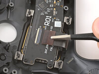
Use a spudger to lift the hinged locking flap on the center ZIF connector.
-
Slide the cable out of the socket and remove it.
-


To reassemble your device, follow these instructions in reverse order.
Take your e-waste to an R2 or e-Stewards certified recycler.
Repair didn’t go as planned? Try some basic troubleshooting, or ask our Answers community for help.
