Introduction
The idea here is to see the different components that make up the device, to understand what they are intended for, how they work independently and also how they interact with each other.
The animation below shows the operation of the pump that will be studied in step 2.
Video Overview
-
-
When the Start button is pressed (Ref. 1), a circuit is closed which powers, via a relay (Ref. 2), the resistive heating element placed in the sole or plate of the iron (Ref. 6). When the desired temperature is reached, a beep is heard (after about 2 minutes)
-
After the beep, steam can be produced by pressing the button in the iron's handle (Ref. 5) Thus, a circuit is closed which turns on a pump placed in the frame beneath the water tank. (Ref. 3) This pump, placed between the tank (Ref. 4) and the iron makes water flow from one to the other.
-
The water, reaching the iron's sole through flexible tubing, turns to steam on contact with the heating element. Indeed, the heat (about 130°C-160°C), turns the water to steam which escapes through the holes in the sole. Releasing the button stops both pump and steam.
-
-
-
The device is composed of several subassemblies that we will look at seperately. We begin with the water pump.
-
This kind of pump, called a suction or vacuum pump, is frequently found in devices requiring pressurization of liquids, usually water. We can therefor find them in espresso coffee makers (pressurized hot water for steam extraction), and in iron steam generators.
-
The axial movement of a metallic piston (Ref. A), open at both ends so as to allow the flow of water, creates the pressure in the system. The 'back and forth' is produced by a magnetic field created by a coil. You can see these parts by following the link at the end of this step.
-
The coil contains a diode in series with the winding, which allows power from a single-phase, full-wave rectified voltage. Put simply, the piston follows the electrical current (50hz) and oscillates with 25 'backs' and 25 'forths' per second.
-
This pronounced vibration is the source of the very characteristc sound of a functioning pump.
-
Water enters one side of the pump (yellow arrow), passes via the cylinder (Ref. A) arrives in the pink chamber. This chamber alternately closed by two valves, pink (Ref. B) and blue (Ref. C). The pink one allows water to enter the chamber when the piston is 'back', the blue one being automatically closed (due to back-pressure).
-
When the piston is driven 'forth', the pink valve closes, the chamber is pressurized, forcing the blue valve open and letting the water through. This cycle repeats 25 times per second.
-
-
-
-
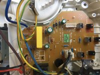
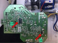
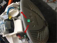
The device has a printed circuit board (PCB) located in the base of the tank. The operation of the device is entrusted to a microcontroller (Ref. 15)(PIC16F1820). This manages the inputs-outputs of the device connected to the various elements, probe, sensor, pump and control panel in order to ensure proper heating of the iron and steam generation.
-
Iron sole-plate temperature management. Is carried out by means of a probe placed in contact with the sole-plate. This iron does not have a manual thermostat to adjust the temperature of the iron. The temp is fixed and is controlled by the probe (see next step in Ref. 8) The temp measured on the sole-plate of the iron is 160°C.
-
Pump flow management using a BT168 GW thyristor (Ref. 16)(BT168 GW). This allows the volume of steam to be reduced in ECO mode or increased in TURBO mode and the descaling function. (see the tutorial for various functions the device controls)
-
Iron Tilt management. This iron has a tilt or motion sensor (Ref. 12). This, in the form of a capsule containing a metal ball. When the iron is horizontal, the ball closes a contact, allowing the heating element to heat up. When the iron is tilted (on its base for example), the circuit is open, and the heating element turned off.
-
Descaling management By pressing the descale button, the pump operates for 2 minutes uninterrupted at the maximum flow rate. The iron signals when descaling is needed. The micro-controller is programmed to manage this alert and will block the pump from working if the operation is not started.
-
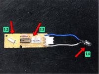
Light and sound signal management. 3 LEDs are placed on the printed circuit opposite each button of the control panel as well as a buzzer. The signals emitted by these components are described in step 3 of the "different functions" tutorial. Another led (Ref. 14) is connected to a small PCB board placed in the handle of the iron.
-
This small PCB board also supports the steam switch (Ref. 13) which is activated by the steam button (Ref. 5) and the tilt sensor (Ref. 12).
-
-
-
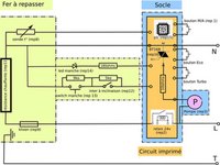
The electrical circuit is made up of a power cord with 3 conductors: Phase (brown), Neutral (blue), and Ground (green/yellow). These three wires are connected to the electronic board. The ground wire is connected to the iron through a protective sheath.
-
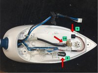
In this sheath are also the wires that will power the heating element (Ref. 11) via the Klixon protection (Ref. 9) and the temperature probe (Ref. 8) as well as the control wires (ON button, LED, etc.) which are in the handle of the iron. The tube through which water flows (Ref 10). is here too.
-
The attached diagram shows the main components and their connections.
-
-
-
The hydraulic (water) system is as follows (red): the water is stored in the reservoir (Ref. 4) When the user requests steam by pressing the button placed in the handle of the iron (Ref. 5), the pump (Ref 3) is started. The water is then sucked up and sent through the tube (Ref. 10) to the sole of the iron (Ref. 6).
-
A safety bypass is located at the pump outlet (Ref. 17) If the water cannot be ejected (clogged tube) it returns to the tank (green).
-


Now that we know the functionalities of our device and we know the sub-assemblies and the operation, we can move on to the repair phase with the following tutorial: "Steam iron, Step 3: common breakdowns" (Please note that this page is currently untranslated.)
Cancel: I did not complete this guide.
21 other people completed this guide.
Special thanks to these translators:
100%


These translators are helping us fix the world! Want to contribute?
Start translating ›

Team

6 Guide Comments
Thank you for this guide, identifying the components was helpful. If there are some links for troubleshooting the pump system you would recommend, I would appreciate it as well. Let's make things repairable :)
Thank you for this guide, identifying the components was helpful.
Same problem happened with me also. Pump of my iron is not working and it is very difficult to find the same in India. If there are some links for troubleshooting the pump system you would recommend, I would appreciate it as well. Let's make things repairable :)
Does your pump run when you press the calc button?
You shared very useful information, thank you very-very-very much!!!