Introduction
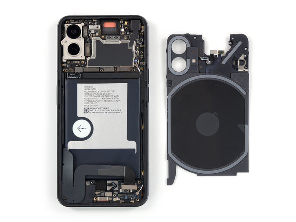
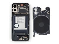
Use this guide to remove the LED glyph assembly in the Nothing Phone (1) including the rear camera cover, flash assembly and motherboard cover.
You’ll need replacement adhesive to reattach the rear glass when reassembling the device. Your device will function normally, but will most likely lose its IP (Ingress Protection) rating.
What you need
-
-
-
Prepare an iOpener and apply it to the rear glass for at least two minutes to loosen the adhesive underneath.
 Ask FixBot
-
-
-
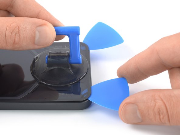
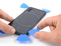
Secure a suction handle to the bottom edge of the rear glass, as close to the edge as possible.
-
Lift the rear glass with the suction handle to create a small gap between the back cover and the frame.
-
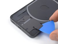
Insert an opening pick into the gap you created.
-
Slide the opening pick to the bottom right corner to slice the adhesive.
-
Leave the opening pick in place to prevent the adhesive from resealing.
-
-
-
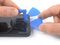
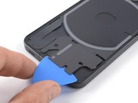
Insert a second opening pick at the bottom edge of your phone.
-
Slide the opening pick to the bottom left corner to slice the adhesive.
-
Leave the opening picks in place to prevent the adhesive from resealing.
-
-
-
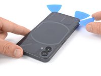
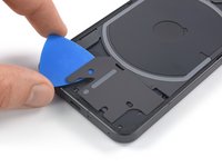
Insert a third opening pick at the bottom left corner of your phone.
-
Slide the opening pick along the left edge of your phone to slice the adhesive.
-
Leave the opening pick in the top left corner to prevent the adhesive from resealing.
-
-
-
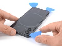
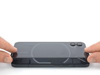
Insert a fourth opening pick underneath the top left corner of your phone.
-
Slide the opening pick along the top edge to slice the adhesive.
-
Leave the opening pick in the top right corner to prevent the adhesive from resealing.
-
-
-
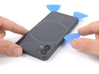
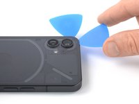
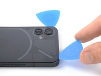
Insert a fifth opening pick underneath the top right corner.
-
Slide the opening pick along the right edge of the rear glass to slice the remaining adhesive.
-
-
Tool used on this step:Dust Blower$5.99
-
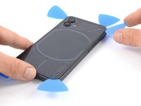
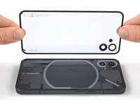
Remove the rear glass.
-
-
-
-
-
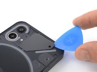
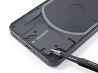
Insert an opening pick underneath the grey plastic cover at the top edge of your phone.
-
Use your opening pick to pry up the plastic cover.
-
Remove the plastic cover.
-
-
-
Use a Torx T5 screwdriver to remove the two 4.2 mm-long screws securing the earpiece speaker.
-
-
Tool used on this step:Tweezers$4.99
-
Insert the flat end of a spudger underneath the bottom edge of the earpiece speaker.
-
Use your spudger to pry up the earpiece speaker.
-
Use a pair of tweezers or your fingers to remove the earpiece speaker.
-
-
-
-
-
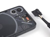
Use a spudger to disconnect the flash assembly cable by prying the connector straight up from its socket.
-
Use a spudger to disconnect the LED glyph cable by prying the connector straight up from its socket.
-
-
Tool used on this step:Tweezers$4.99
-
Insert an opening pick underneath the recording indicator light cover at the top right corner of the screen.
-
Use your opening pick to pry up the plastic cover.
-
Use a pair of tweezers or your fingers to remove the recording indicator light cover.
-
-
-
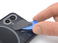
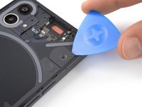
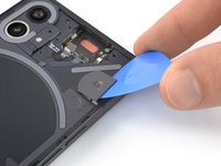
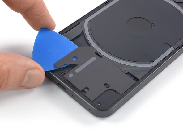
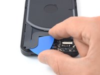
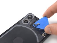
Slide an opening pick underneath the right, bottom and left edge of the bottom LED assembly to carefully separate it from the daughterboard cover.
-
-
-
-
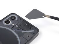
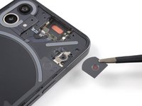
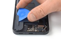
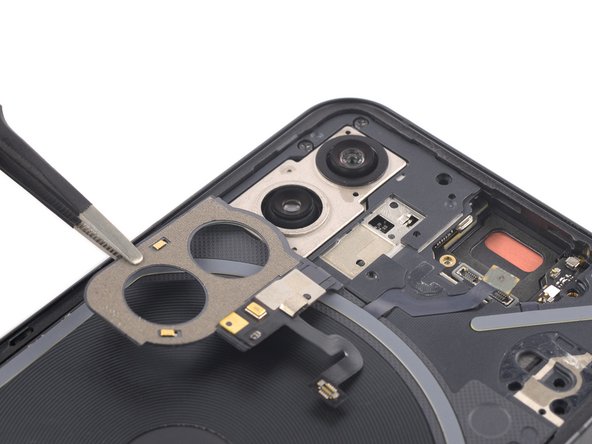
Use a pair of blunt nosed tweezers and carefully fold the bottom LED assembly over to get free access to the LED cable connector.
-
-
-
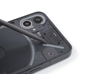
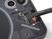
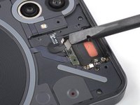
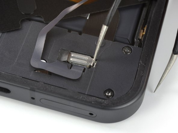
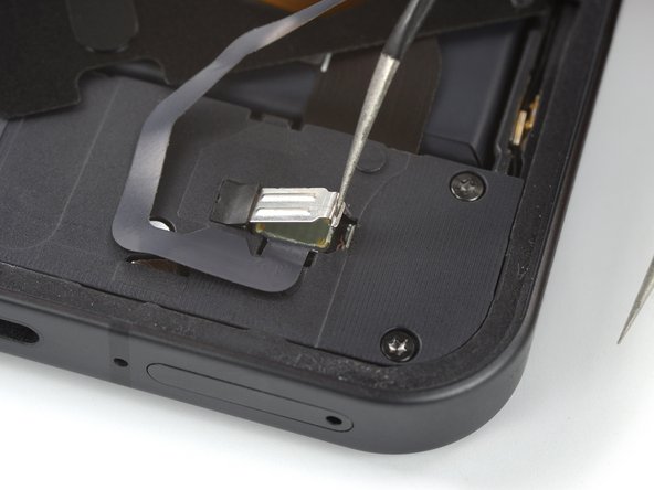
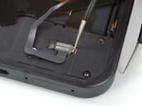
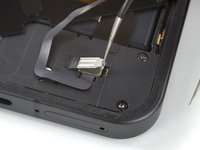
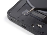
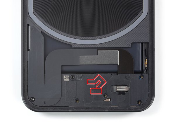
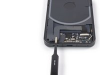
Insert one arm of a pair of tweezers into the gap at the right side of the connector bracket.
-
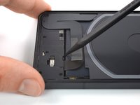
Push your tweezers toward the left edge of the phone to free the closure flap of the connector bracket.
-
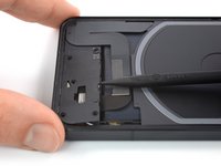
Lift the connector bracket with your tweezers to access the LED connector.
-
-
-
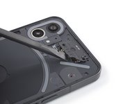
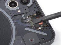
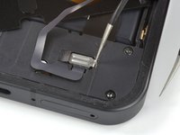
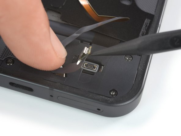
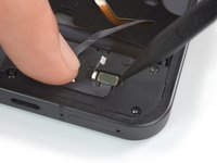
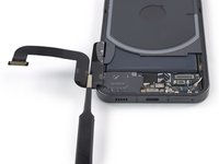
Use a spudger to disconnect the LED cable by prying the connector straight up from its socket.
-
-
-
Use a pair of tweezers or your fingers to remove the bottom LED assembly.
-
-
-
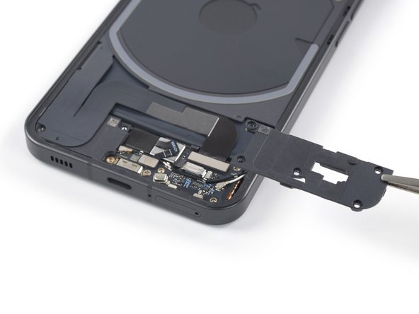
Use a Torx T5 screwdriver to remove the five 4.2 mm-long screws securing the daughterboard cover.
-
-
-
Use a pair of tweezers to carefully separate the grey plastic shield from the daughterboard cover and remove it.
-
-
-
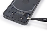
Insert the pointed end of a spudger underneath the top edge of the daughterboard cover just above the black rubber guard securing the LED connector bracket.
-
Pry up with the spudger to release the daughterboard cover from its clips.
-
-
-
Use a pair of tweezers or your fingers to remove the daughterboard cover.
-
-
-
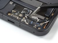
Use a pair of tweezers to remove the black rubber guard securing the LED connector bracket.
-
-
-
Use a pair of tweezers to remove the LED connector bracket.
-
-
-
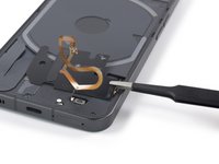
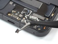
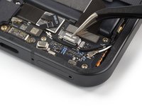
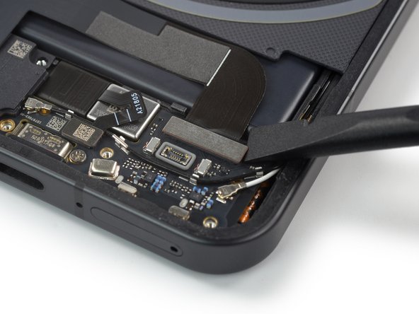
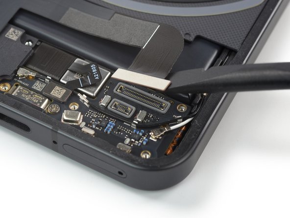
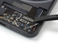
Use a spudger to disconnect the interconnect cable by prying the connector straight up from its socket.
-
-
-
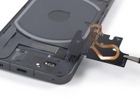
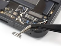
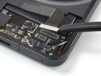
Carefully slide an opening pick underneath the interconnect cable to separate it from the charging coil assembly and the loudspeaker.
-
-
-
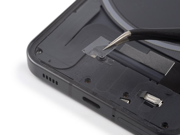
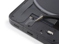
Use a pair of tweezers to fold the interconnect cable to the left like you'd open the cover of a book.
-
-
-
Use a Torx T5 screwdriver to remove the four 4.2 mm-long screws securing the motherboard cover.
-
-
-
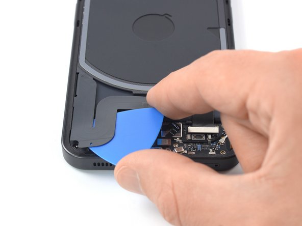
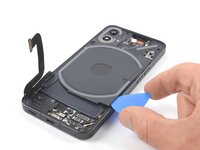
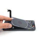
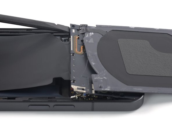
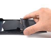
Insert an opening pick underneath the bottom right edge of the charging coil assembly.
-
Slide the opening along the right edge of the charging coil assembly to separate the adhesive.
-
-
-
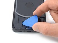
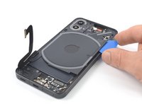
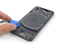
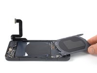
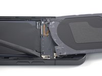
Insert an opening pick underneath the bottom left edge of the charging coil assembly.
-
Slide the opening along the left edge of the charging coil assembly to separate the adhesive.
-
-
-
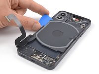
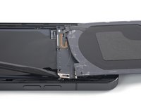
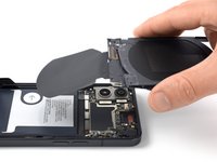
Carefully fold the charging coil to the top edge of the phone to access the motherboard cover screws.
-
-
-
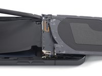
Use a Phillips screwdriver to remove the three 4.2 mm-long screws securing the motherboard cover.
-
-
-
Return the charging coil to its original position.
-
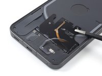
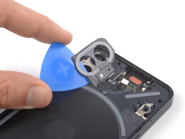
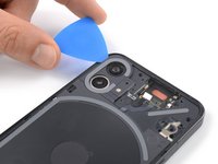
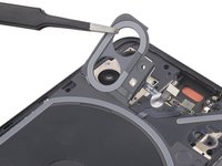
Carefully slide an opening pick underneath the camera cover and flash assembly to separate it from the motherboard cover.
-
-
-
Use a pair of tweezers to carefully fold the camera cover and flash assembly toward the battery.
-
-
-
Use a Torx T5 screwdriver to remove the two 4.2 mm-long screws securing the motherboard cover.
-
Return the camera cover and flash assembly to its original position.
-
-
-
Carefully fold the charging coil to the top edge of the phone to access the bottom edge of the motherboard cover.
-
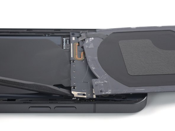
Insert the flat end of a spudger underneath the bottom right edge of the motherboard cover.
-
Pry up with the spudger to release the motherboard cover from its clips.
-
Repeat the prying procedure for the bottom left edge of the motherboard cover.
-
-


To reassemble your device, follow these instructions in reverse order.
Take your e-waste to an R2 or e-Stewards certified recycler.
Repair didn’t go as planned? Try some basic troubleshooting, or ask our Answers community for help.
Cancel: I did not complete this guide.
3 other people completed this guide.

