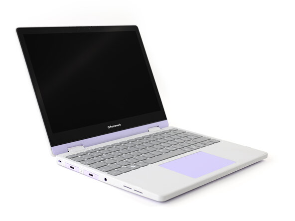
Introduction
Follow this guide to replace or upgrade the Mainboard in your Framework Laptop 12.
The Mainboard (aka motherboard) is responsible for the primary functions for your laptop. If you want to upgrade your processor, you'll need to replace the Mainboard.
Replacement Mainboard kits come with the fan and heatsink pre-attached, so you don't need to worry about applying thermal compound to the processor.
You'll encounter some component terms in this guide:
- The Input Cover is the part that contains the keyboard and trackpad.
What you need
-
-
Make sure you back up your data.
-
If you’re running a Pro version of Windows, suspend BitLocker by following these directions.
-
If you're running a Home version of Windows and have enabled Windows Device Encryption, you will want to disable it. To disable it, press Win + I to open Settings and select Privacy & Security. Select Device Encryption, then toggle the Device Encryption setting to Off.
-
Find your product key or link your Windows license to a Microsoft account to make sure you can re-activate Windows after the change.
 Ask FixBot
-
-
-
Before you begin repairs, unplug your laptop and shut it down from the operating system. This ensures that the laptop isn't in standby/suspend mode.
-
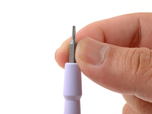
Make sure your Framework Screwdriver has the T5 Torx bit (labeled as T-5) facing outwards. If it's not, pull the bit out and flip it.
-
-
-
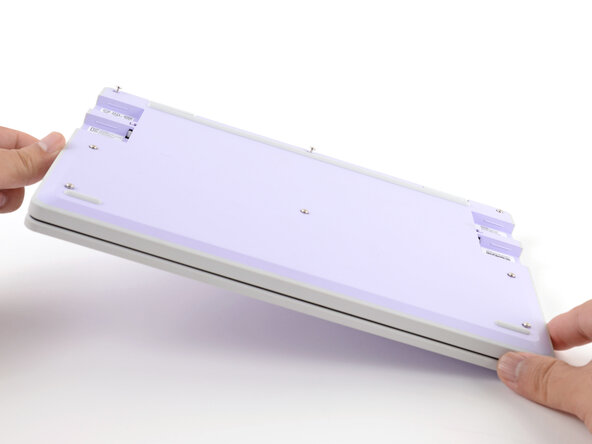
Set your Framework Laptop face-down on a clean work surface.
-
-
-
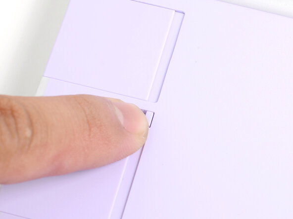
Use your fingers to flip the two Expansion Card latches (one for each side) into the unlocked position.
-
-
-
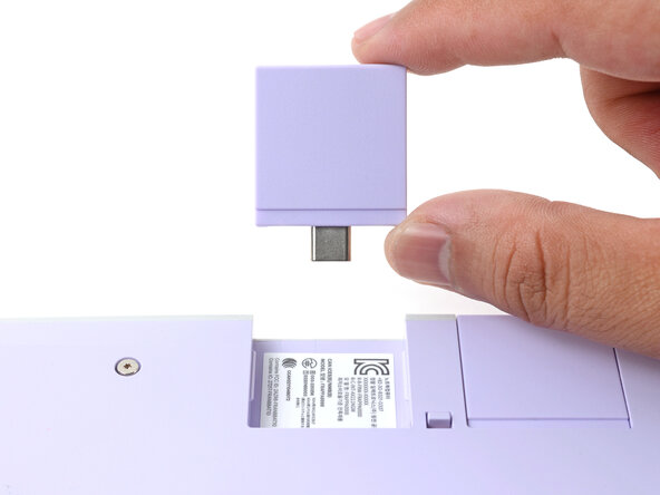
Grip the lip of an Expansion Card with your fingers.
-
Pull the Expansion Card out of its slot and remove it.
-
Repeat this procedure to remove all remaining Expansion Cards.
-
-
-
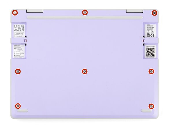
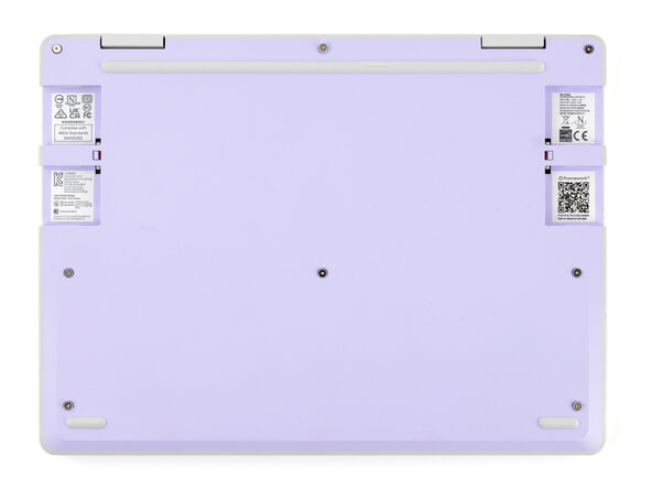
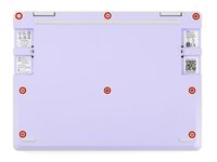
Use your Framework Screwdriver to fully loosen the eight captive T5 Torx screws on the bottom of your laptop.
-
-
-
Open the laptop lid so that both the screen and the base lie flat on your work surface.
-
-
-
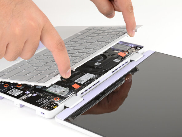
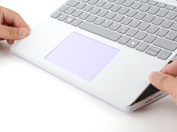
Use your fingers to grip the Input Cover in the hinge cutouts.
-
Lift upwards to swing the Input Cover up from the base of the laptop.
-
Remove the Input Cover.
-
-
-
Use your Framework Screwdriver to loosen the six captive T5 Torx screws securing the battery.
-
-
-
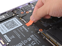
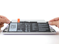
Grab the orange battery tab with your fingers and lift straight up to disconnect the battery.
-
-
-
Use your fingers to spread the clips on both sides of the memory module apart to unclip the memory.
-
-
-
Use your fingers to grab the memory module by its edges.
-
Slide the memory module out of its socket and remove it.
-
-
-
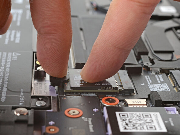
Use your finger to press down on the black SSD latch to unlatch the SSD.
-
-
-
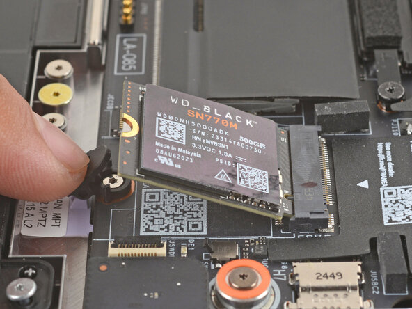
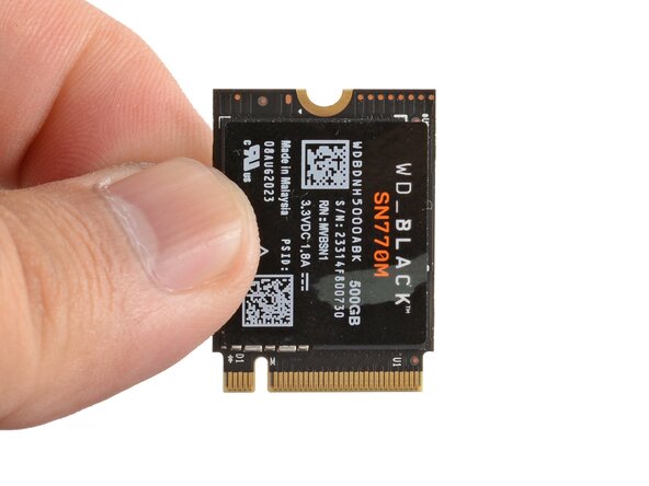
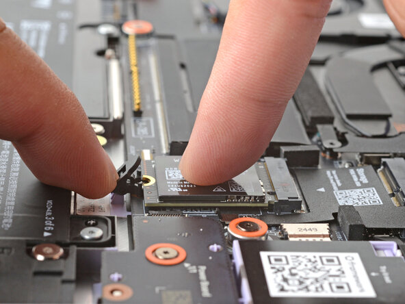
Grab the SSD by its edges and pull it out of its socket.
-
Remove the SSD.
-
-
-
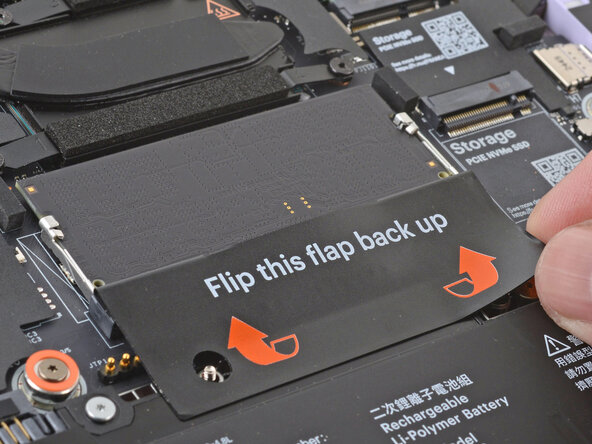
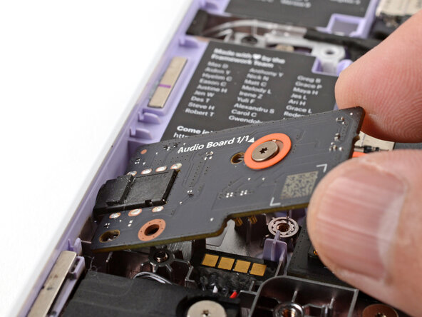
Use your Framework Screwdriver to loosen the captive T5 Torx screw securing the Audio Board along the left edge of the laptop.
-
-
-
-
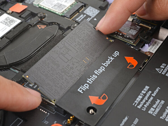
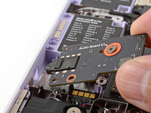
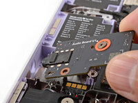
Use your fingers to lift the right edge of the Audio Board and pull it out of its recess.
-
Remove the Audio Board.
-
-
-
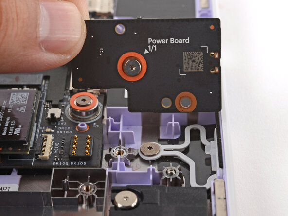
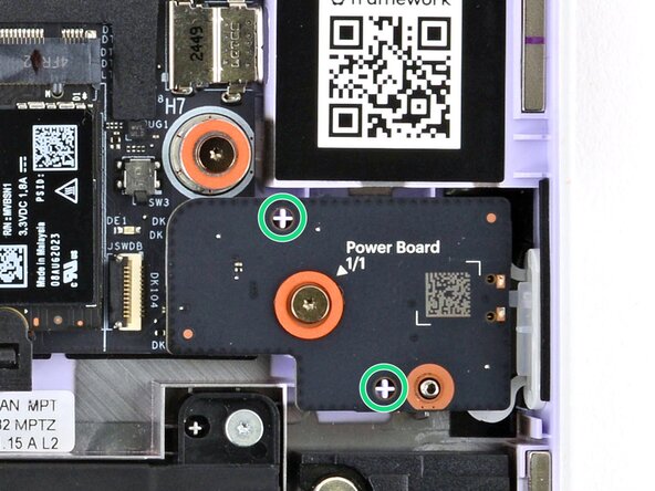
Use your Framework Screwdriver to loosen the captive T5 Torx screw securing the Power Button Board (labeled "Power Board").
-
-
-
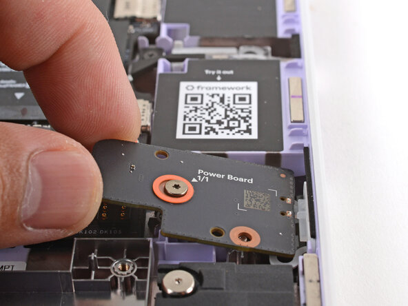
Use your fingers to lift and remove the Power Button Board.
-
-
-
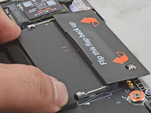
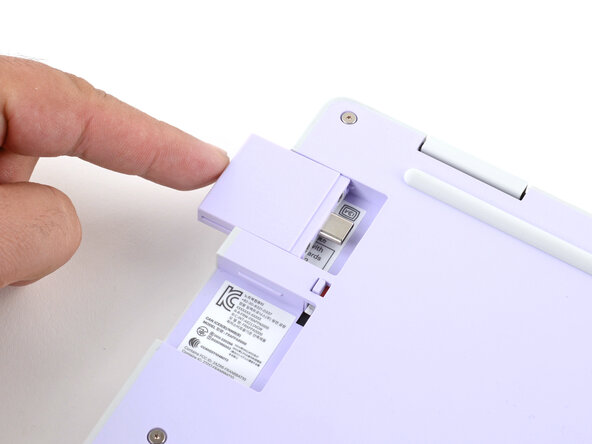
Use your Framework Screwdriver to loosen the captive T5 Torx screw securing the Wi-Fi card bracket.
-
-
-
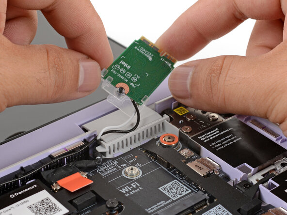
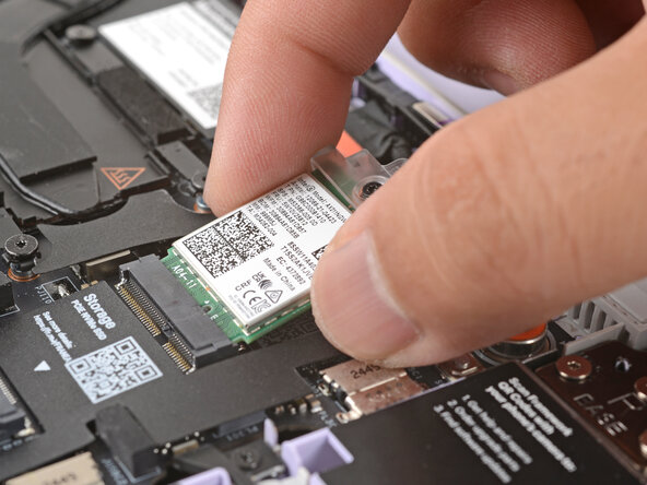
Grab the Wi-Fi card by its edges and slide it out of its socket.
-
-
-
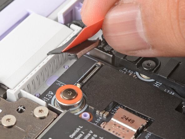
Use your fingers to grab the orange tab on the webcam cable, located near the left hinge.
-
Lift straight up to disconnect the cable.
-
-
-
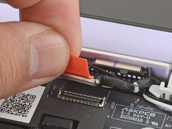
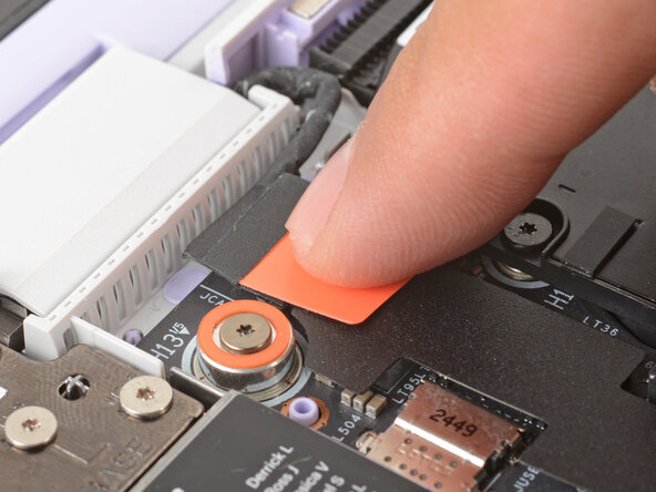
Use your fingers to grab the orange tab on the display cable, located near the right hinge.
-
Lift straight up to disconnect the cable.
-
-
-
Use your Framework Screwdriver to loosen the five captive T5 Torx screws securing the Mainboard.
-
-
-
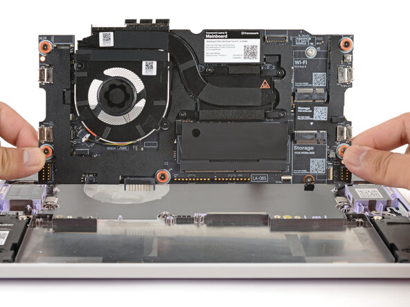
Use your fingers to grab the Mainboard by its edges.
-
Lift and remove the Mainboard.
-
-
-
Carefully lay the Mainboard in the laptop.
-
Use the two alignment pins to help align the Mainboard to the laptop.
-
Be careful not to trap the webcam or display cables under the Mainboard as you set it in place.
-
-
-
Use your Framework Screwdriver to tighten the five captive T5 Torx screws to secure the Mainboard.
-
-
-
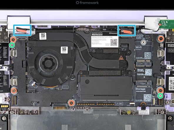
Use your fingers to grab the display cable by its orange tab.
-
Align and press the display cable straight down onto its connector.
-
-
-
Use your fingers to grab the webcam cable by its orange tab.
-
Align and press the webcam cable straight down onto its connector.
-
-
-
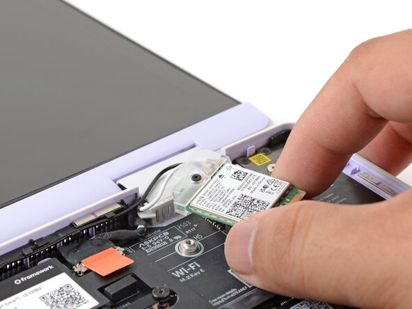
Use your fingers to carefully move the Wi-Fi card over the Mainboard.
-
-
-
Align the Wi-Fi card's gold contacts and notch with the socket on the Mainboard.
-
Insert the Wi-Fi card into the socket at a shallow angle. The gold contacts should mostly be covered by the socket.
-
-
-
Hold the Wi-Fi card down with your finger.
-
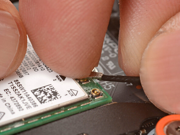
Position the black antenna cable connector over the left Wi-Fi card's coaxial socket.
-
Use your finger to press the connector into place. You should feel a faint click, and the cable will stay attached to the socket by itself.
-
Repeat the procedure with the white antenna cable.
-
-
-
Use your Framework Screwdriver to tighten the captive T5 Torx screw to secure the Wi-Fi card.
-
-
-
Use your fingers to lay the Power Button Board in place.
-
Use the two plastic pins on the laptop to align the Power Button Board.
-
-
-
Use your Framework Screwdriver to tighten the captive T5 Torx screw to secure the Power Button Board.
-
-
-
Insert the Audio Board into the laptop at an angle to help align the headphone jack.
-
Use the two plastic alignment pins on the laptop to help with final alignment.
-
-
-
Use your Framework Screwdriver to tighten the captive T5 Torx screw to secure the Audio Board.
-
-
-
Align the SSD's gold contacts with its socket.
-
Insert the SSD into the socket at a shallow angle. The gold contacts should mostly be covered by the socket.
-
-
-
Use your finger to press down on the black SSD latch to keep it open.
-
Use another finger to press the SSD down until it lays flat.
-
Use your finger to close the latch to secure the SSD.
-
-
-
Orient the module with the label facing down and align the gold contacts with the socket.
-
Insert the contact edge into the socket at a shallow angle. The gold contacts should mostly be covered by the socket.
-
Press the edges of the memory module down until the side clips lock it in place.
-
-
-
Use your finger to push the battery down near its connector to reconnect it.
-
-
-
Use your Framework Screwdriver to tighten the six captive T5 Torx screws to secure the battery.
-
-
-
Angle the bottom edge of the Input Cover towards the base of the laptop.
-
Align and insert the bottom edge of the Input Cover into the base of the laptop.
-
Lower the Input Cover's top edge onto the laptop until the magnets snap it in place.
-
-
-
Use your Framework Screwdriver to tighten the eight captive T5 Torx screws on the bottom of your laptop.
-
-
-
Slide each Expansion Card into its Expansion Card slot.
-


You finished fixing your Framework Laptop!
Take your e-waste to an R2 or e-Stewards certified recycler.
If you need help, contact Framework support.

Team
