Introduction
Follow the steps in this guide to replace the loudspeaker in an iPhone 7. This guide includes instructions for removing the speaker assembly, and peeling off the Wi-Fi diversity antenna which needs to be transferred to your new loudspeaker.
What you need
Video Overview
-
-
Power off your iPhone before beginning disassembly.
-
Remove the two 3.4 mm pentalobe screws on the bottom edge of the iPhone.
-
-
-
Use a hairdryer or prepare an iOpener and apply it to the lower edge of the iPhone for about a minute in order to soften up the adhesive underneath.
-
-
-
Pull up on the suction cup to create a small gap between the display assembly and the rear case.
-
Insert the flat end of a spudger into the gap.
-
-
-
Slide the spudger to the left along the lower edge of the iPhone.
-
Twist the spudger to widen the gap between the display and rear case.
-
-
-
Slide the spudger up the left side of the iPhone, starting at the lower edge and moving towards the volume control buttons and silent switch.
-
-
-
Insert the flat edge of a spudger into the bottom right corner of the device.
-
Twist the spudger to widen the gap between the display assembly and the rear case.
-
Slide the flat end of the spudger up the right side of the phone to break up the adhesive holding the display in place.
-
-
-
Slide an opening pick along the top edge of the iPhone, between the rear case and front panel, to break up the remaining adhesive holding the screen in place.
-
-
-
Pull the display assembly slightly away from the top edge of the phone to disengage the clips holding it to the rear case.
-
Open the iPhone by swinging the display up from the left side, like the back cover of a book.
-
-
-
-
Remove four tri-point Y000 screws securing the lower connector bracket, of the following lengths:
-
Three 1.2 mm screws
-
One 2.4 mm screw
-
-
-
Use the point of a spudger to lift the battery connector out of its socket on the logic board.
-
-
-
Use a spudger or a fingernail to disconnect the two lower display connectors by prying them straight up from their sockets on the logic board.
-
-
-
Remove the two 1.3 mm Phillips #000 screws securing the bracket over the front panel sensor assembly connector.
-
-
-
Remove the two 1.9 mm Phillips screws securing the barometric vent to the rear case.
-
-
-
Use the flat end of a spudger to disconnect the Taptic Engine connector from its socket on the logic board.
-
-
-
Remove the Phillips screw securing the Wi-Fi diversity antenna to the rear case:
-
One 3.2 mm screw
-
-
-
Remove the following three Phillips screws securing the speaker to the rear case:
-
Two 1.3 mm screws
-
One 2.0 mm screw
-
-
-
Use the point of a spudger to lift the two antenna cable connectors up off of the sockets on the logic board.
-
-
-
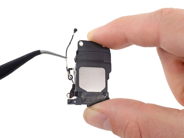
Use the tip of a spudger to slide the speaker assembly towards the logic board and off of the rear case.
-