Introduction
Follow this guide to replace the power supply in your Valve Steam Machine (2026).
If your Steam Machine isn't turning on, has intermittent power, or randomly shuts down, it might be time to replace the power supply.
Before starting this repair, test your Steam Machine with both a different power cable and on a different power outlet to make sure the problem is actually the power supply itself.
Warning: Don't attempt to disassemble the power supply itself. Internal components can retain a dangerous electrical charge even when unplugged.
What you need
-
-
-
Power down your Steam Machine and disconnect the power cable.
-
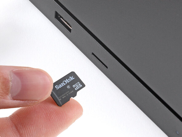
Unplug any remaining cables or accessories from all ports.
 Ask FixBot
-
-
-
-
-
Reposition the Steam Machine so the bottom is facing up.
-
-
-
-
-
Reposition the Steam Machine so the back panel is facing up.
-
-
-
Use a T8 Torx screwdriver to fully loosen the two captive screws securing the back panel.
-
-
-
Lift the top edge of the panel (near the screws) until the two locking clips release.
-
Slide the panel towards the top edge and lift to remove it.
-
-
-
Use a T8 Torx screwdriver to remove the two 7.3 mm‑long screws securing the inner assembly.
-
-
-
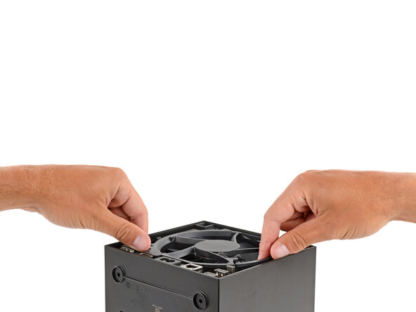
Grip the inner assembly under the fan and lift it straight up and out of the shell.
-
Set the inner assembly down so the SSD is on top.
-
-
-
-
-
Use a T8 Torx screwdriver to remove the 5.1 mm‑long screw securing the rear USB and Ethernet port cable cover.
-
-
-
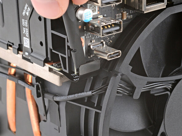
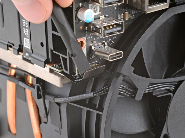
Use the flat end of a spudger to pry up and disconnect the board's press connector.
-
-
-
Use a T8 Torx screwdriver to remove the 5.1 mm‑long screw securing the rear USB and Ethernet port board.
-
-
-
Slide the board straight away fron the inner assembly to remove it.
-
-
-
-
Reposition the inner assembly so the antenna marked AUX ANT is facing up.
-
-
-
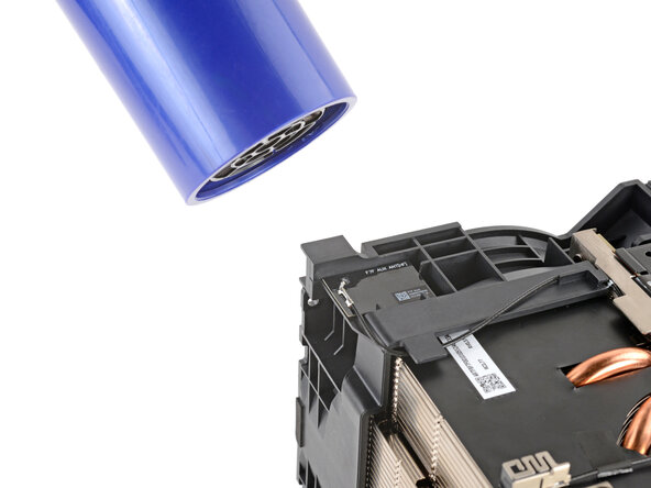
Lay a heated iOpener on the auxiliary antenna for two minutes.
-
-
Tool used on this step:Tesa 61395 Tape$2.95
-
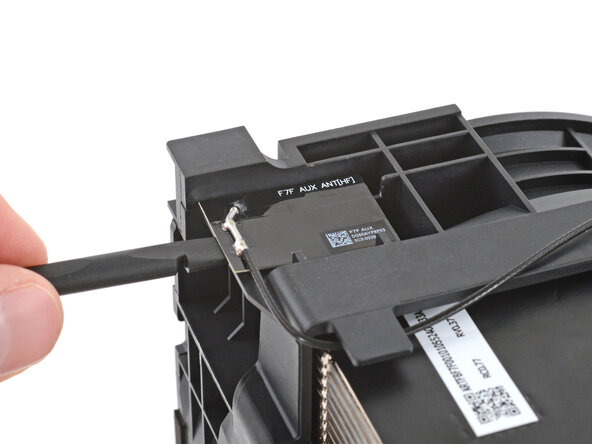
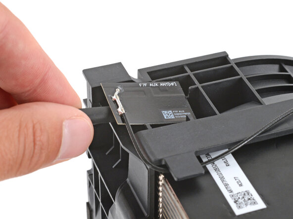
Slide the flat end of a spudger under the antenna and lift to separate the adhesive.
-
-
-
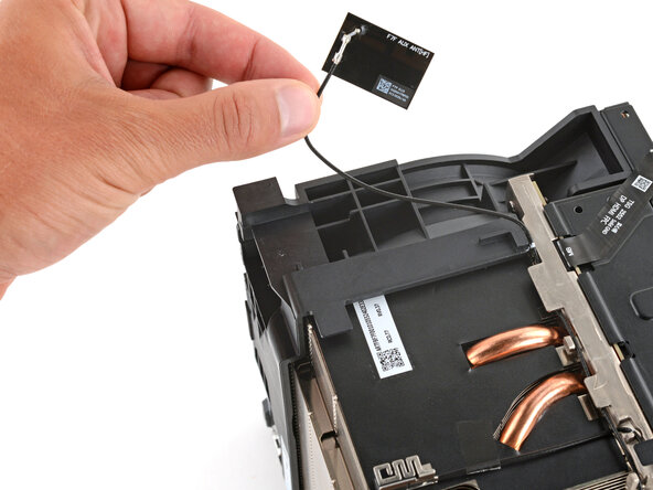
Guide the antenna cable out of its clips on the fan.
-
-
-
Reposition the inner assembly so the antenna marked MAIN ANT is facing up.
-
-
-
-
Lay a heated iOpener on the main antenna for two minutes.
-
-
Tool used on this step:Tesa 61395 Tape$2.95
-
Slide the flat end of a spudger under the antenna and lift to separate the adhesive.
-
-
-
Use a pair of angled tweezers to firmly grip the head of the fan cable connector.
-
Gently rock the connector side-to-side while lifting to disconnect it.
-
-
-
Peel up the tape securing the fan cable to the heatsink.
-
-
-
Reposition the inner assembly so the fan is facing you and the power cable socket is on the bottom.
-
-
-
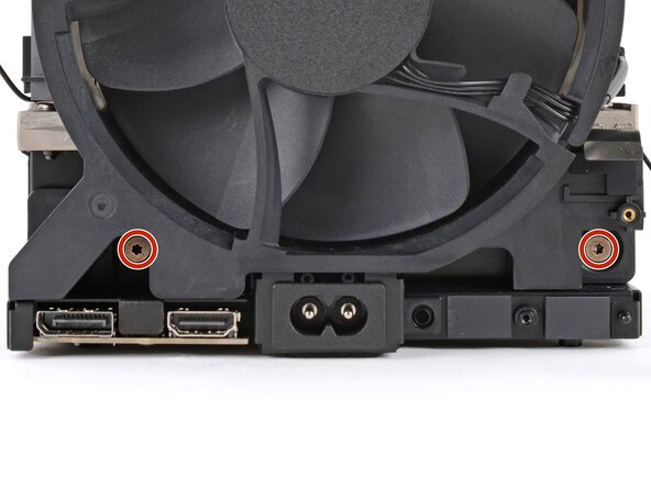
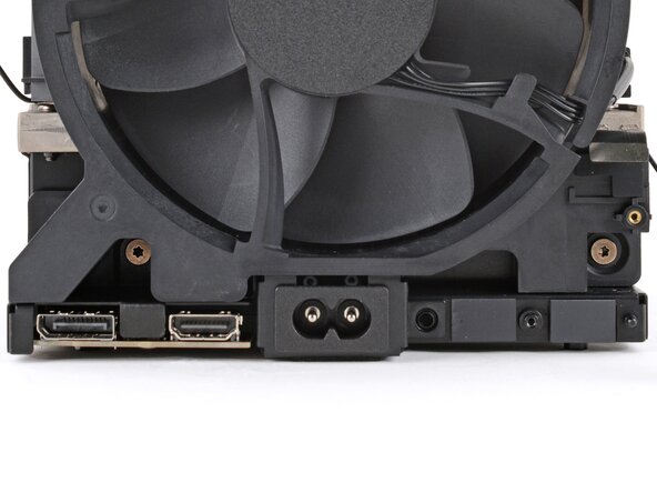
Use a T8 Torx screwdriver to remove the two 7.3 mm‑long screws securing the fan.
-
-
-
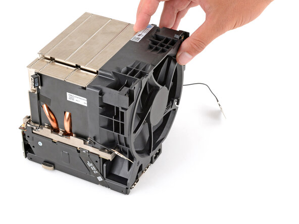
Slide the fan straight away from the inner assembly to remove it.
-
-
-
-
-
Reposition the inner assembly so the microSD reader and two USB ports are facing up at the top edge farthest from you.
-
-
-
Use a T8 Torx screwdriver to remove the two 5.1 mm‑long screws securing the front port cable cover.
-
-
-
Use the flat end of a spudger to pry up and disconnect the board's press connector.
-
-
-
Use the point of a spudger to lift and disconnect the three coaxial connectors, making sure to lift as close to the connector head as possible.
-
-
-
Reposition the inner assembly so the microSD and two USB ports are at the top edge closest to you.
-
-
-
Use a T8 Torx screwdriver to remove the two 5.1 mm‑long screws securing the HDMI and DisplayPort cable cover.
-
-
-
Use the flat end of a spudger to pry up and disconnect the press connector on the HDMI and DisplayPort board.
-
-
-
Use your fingers to gently peel the HDMI and DisplayPort board's cable off the metal frame.
-
-
-
Use a T8 Torx screwdriver to remove the 5.1 mm‑long screw securing the SSD.
-
-
-
Pull the SSD out of its socket at the angle it popped up at to remove it.
-
-
-
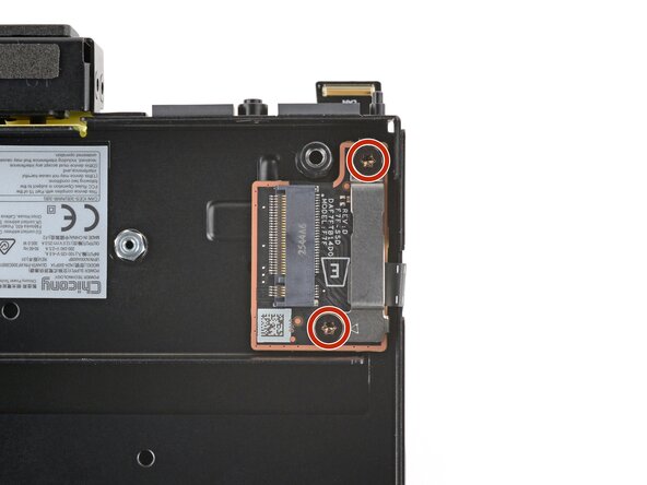
Use a T8 Torx screwdriver to remove the two 5.1 mm‑long screws securing the SSD board and its cover.
-
-
-
With one hand, hold the board down by the SSD socket.
-
With your free hand, use the flat end of a spudger to pry up and disconnect the board's press connector.
-
-
-
Use your fingers to gently peel the SSD board cable off the metal frame.
-
-
-
Flip the inner assembly over so the heatsink is on top.
-
-
-
Use a T8 Torx screwdriver to remove the four 12.8 mm‑long screws securing the power supply.
-
-
-
With one hand, firmly secure the power supply.
-
With your free hand, grip under the corner of the inner assembly so you're lifting up on the motherboard itself.
-
Firmly pull the corner up until it disconnects from the power supply.
-
-
-
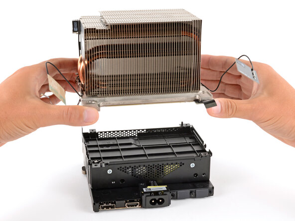
Remove the motherboard and heatsink from the power supply and set it down so the motherboard is facing up.
-
-
-
-
-
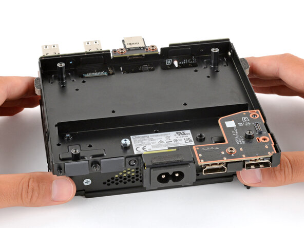
Flip the power supply over and set it down so the power cable socket is facing you.
-
-
-
Use a T8 Torx screwdriver to remove the 5.1 mm‑long screw securing the HDMI and DisplayPort board.
-
-
-
Lift the HDMI and DisplayPort board straight up and remove it.
-
-
-
Reposition the power supply so the power cable socket in facing away from you.
-
-
-
Use a T8 Torx screwdriver to remove the two 5.1 mm‑long screws securing the microSD card reader.
-
-
-
Pull the microSD card reader straight up to disconnect and remove it.
-
-
-
Use a T8 Torx screwdriver to remove the three 5.1 mm‑long screws securing the front port board.
-
-
























To reassemble your device, follow these instructions in reverse order.
Take your e-waste to an R2 or e-Stewards certified recycler.
Repair didn’t go as planned? Try some basic troubleshooting, or ask our Answers community for help.

