Introduction
Use this guide to replace the Bluetooth antenna in your Nintendo Switch.
The Switch uses JIS screws. A JIS 00 driver works best, but you can also use a JIS 000 driver. If you use a Phillips driver, you'll risk stripping the screws.
What you need
-
-
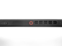
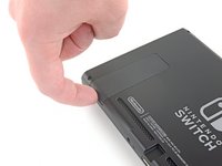
Press and hold down the small round button on the back of the Joy Con controller.
-
While you hold down the button, slide the controller upward.
 Ask FixBot
-
-
-
Continue sliding the Joy Con upward until it's completely removed from the console.
-
-
Tool used on this step:Magnetic Project Mat$19.95
-
Use a Y00 screwdriver to remove the four 6.3 mm-long screws securing the rear panel.
-
-
-
Use a JIS 00 driver to remove the following screws securing the rear panel:
-
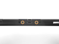
One 2.5 mm-long screw on the top edge of the device
-
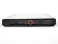
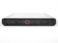
Two 2.5 mm-long screws on the bottom edge of the device
-
-
-
Use a JIS 00 driver to remove the two 3.8 mm center screws on the sides of the device (one on each side).
-
-
-
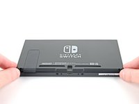
Use your finger to flip up the kickstand on the back of the device.
-
If there's a microSD card in the microSD card slot, remove it now before you continue to the next step.
-
-
-
Use a JIS 00 driver to remove the 1.6 mm screw in the kickstand well.
-
Close the kickstand.
-
-
-
Open the game card cartridge flap.
-
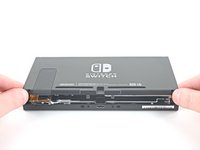
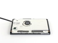
Lift the rear panel straight up from the bottom of the device and remove it.
-
-
-
Use a JIS 00 driver to remove the 3.1 mm screw securing the microSD card reader to the device.
-
-
Tool used on this step:Tweezers$4.99
-
Use your fingers or a pair of tweezers to lift the microSD card reader straight up from the device to disconnect and remove it.
-
-
-
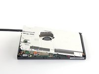
Use a JIS 00 driver to remove the six 3 mm screws securing the shield plate to the device.
-
-
Tool used on this step:Tweezers$4.99
-
Use your fingers or a pair of tweezers to peel back the piece of foam on the top edge of the device near the fan exhaust port.
-
-
Tool used on this step:iFixit Thermal Putty$9.95
-
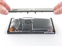
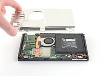
Insert a spudger underneath the shield plate along the edge of the device.
-
Pry up to lift the shield plate and remove it from the device.
-
During reassembly, if you don't have replacement thermal compound, use the flat end of a spudger to distribute the old compound evenly across the heat pipe, as thick as possible to ensure proper contact. Repeat this process on the shield plate.
-
If you need to replace it, refer to our thermal paste guide to remove the old thermal compound and replace it with an appropriate compound, such as thermal putty or K5 Pro, during reassembly.
-
-
-
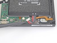
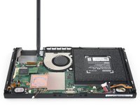
Use the point of a spudger to pry the battery connector straight up and out of its socket on the motherboard.
-
-
-
Use a JIS 00 driver to remove the three 3 mm screws securing the heat sink to the motherboard.
-
-
Tool used on this step:iFixit Adhesive Remover$19.99
-
Carefully peel the two foam pieces stuck over both the heatsink and the fan away from the fan.
-
If you have some, dip the point of a spudger in adhesive remover or isopropyl alcohol (90% or greater).
-
Insert the point of a spudger underneath a part of the foam that isn't stuck to anything.
-
Press the top of the foam with your finger to hold it in place.
-
Roll the spudger tip underneath the foam all the way to the other end of the foam to release it.
-
-
-
Use a spudger or your fingers to lift the heatsink up and off the motherboard to remove it.
-
Apply thermal paste to all surfaces that had thermal paste applied previously. This includes between the heatpipe and aluminum shield, which the Switch uses as additional heatsinking.
-
-
-
Use an opening tool or your fingernail to flip up the small, hinged locking flap on the digitizer cable's ZIF connector.
-
-
Tool used on this step:Tweezers$4.99
-
Use a pair of tweezers to slide the digitizer cable horizontally out of its connector on the game card reader board.
-
-
-
Use the point of a spudger to pry the headphone jack and game card reader connector straight up to disconnect it from the motherboard.
-
-
-
Use a JIS 00 driver to remove the three 3.1 mm screws securing the headphone jack and game card reader board to the device.
-
-
-
Use a pair of tweezers or your fingers to remove the headphone jack bracket.
-
-
-
Use a pair of tweezers or your fingers to remove the headphone jack and game card reader board.
-
-
-
Use an opening tool, spudger, or your fingernail to flip up the small, hinged locking flap on the LCD ribbon cable ZIF connector.
-
-
Tool used on this step:Tweezers$4.99
-
Use a pair of tweezers to pull the ribbon cable straight out of its connector on the motherboard.
-
-
-
-
Use an opening tool, spudger, or your fingernail to flip up the small, hinged locking flap on the fan cable ZIF connector.
-
-
-
Use a pair of tweezers to pull the fan cable straight out of its connector on the motherboard.
-
-
-
Use an opening tool, spudger, or your fingernail to flip up the small, hinged locking flap on the power and volume button ribbon cable ZIF connector.
-
-
-
Use a pair of tweezers to pull the ribbon cable straight out of its connector on the motherboard.
-
-
-
Use an opening tool, spudger, or your fingernail to flip up the small, hinged locking flap on the smaller LCD ribbon cable ZIF connector.
-
-
-
Use a pair of tweezers to pull the ribbon cable straight out of its connector on the motherboard.
-
-
-
Use the point of a spudger, an opening tool, or your fingernail to flip up the small, hinged locking flap on the Joy Con sensor rail's data cable ZIF connector.
-
-
-
Use a pair of tweezers to pull the ribbon cable straight out of its connector on the motherboard.
-
-
-
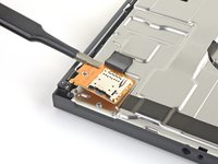
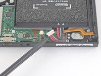
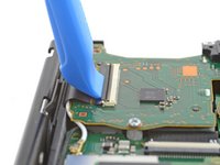
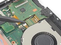
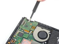
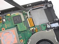
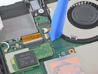
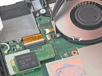
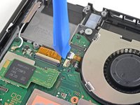
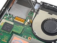
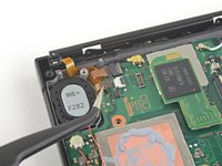
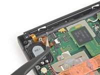
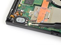
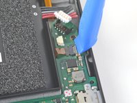
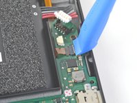
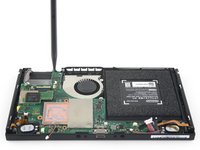
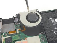
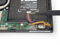
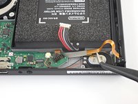
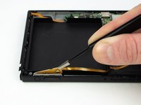
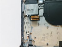
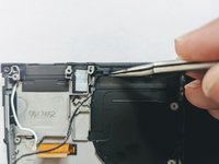
Use the point of a spudger to pry up the black antenna cable straight up out of its socket on the motherboard.
-
-
-
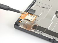
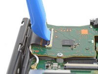
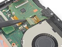
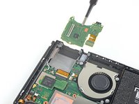
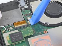
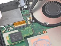
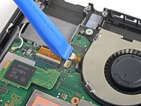
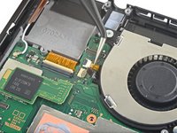
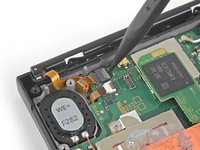
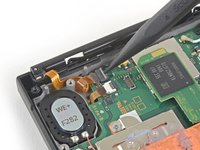
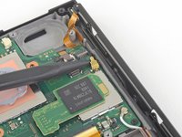
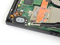
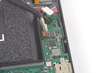
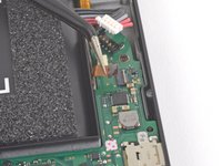
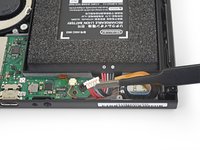
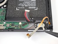
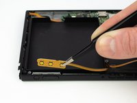
Use the point of a spudger to pry up the white antenna cable straight up out of its socket on the motherboard.
-
-
-
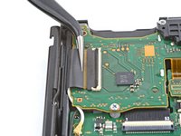
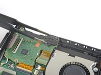
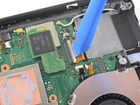
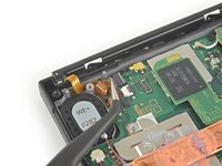
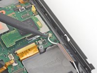
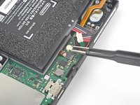
Use your fingers or a pair of tweezers to pull the right speaker connector straight out of its socket on the motherboard.
-
-
-
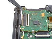
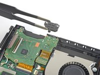
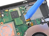
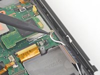
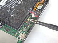
Use your fingers or a pair of tweezers to pull the left speaker connector straight out of its socket on the motherboard.
-
-
-
Use an opening tool, spudger, or your fingernail to flip up the small, hinged locking flap on the Joy Con sensor rail data cable ZIF connector.
-
-
-
Use a pair of tweezers to slide the Joy Con rail data cable straight out of its connector on the motherboard.
-
-
-
Use a JIS 00 driver to remove the following screws:
-
Four 2.5 mm screws
-
Two 3.1 mm screws
-
-
-
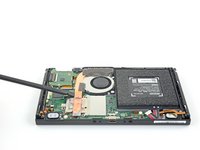
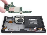
Insert a spudger into a gap between the motherboard and the frame.
-
Carefully lift up the motherboard and remove it from the frame.
-
-
-
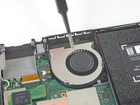
Use a JIS 00 driver to remove the three 4.8 mm screws securing the fan.
-
-
Tool used on this step:Tweezers$4.99
-
Use a pair of tweezers or your fingers to lift the fan straight up and remove it from the device.
-
-
-
Use a JIS 00 driver to remove the four 3.7 mm screws securing the right Joy Con rail to the frame of the device.
-
-
-
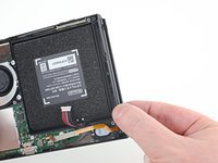
Use your fingers or a pair of tweezers to lift the battery connector up and out of the way of the Joy Con rail's data cable.
-
-
-
Use your fingers or a pair of tweezers to lift the battery connector up and out of the way of the Joy Con rail's data cable.
-
-
-
Use a JIS 00 driver to remove the four 3.7 mm screws securing the left Joy Con rail to the frame of the device.
-
-
-
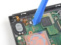
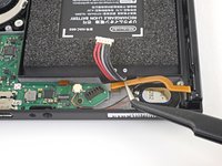
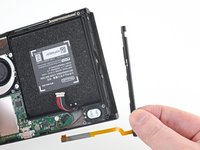
Use the flat end of a spudger to pry up the taped down power/volume ribbon cable.
-
-
-
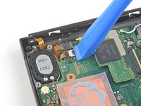
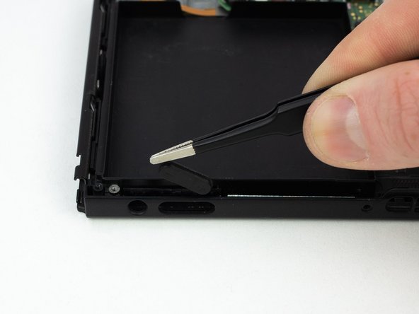
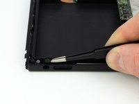
Pull the rubber conductive pad out with a pair of blunt nose tweezers.
-
-
-
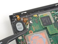
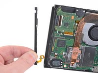
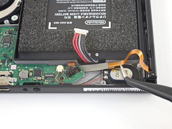
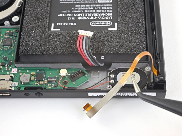
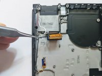
Grasp the WiFi antenna board with a pair of tweezers and lift straight up to remove it.
-
-
-
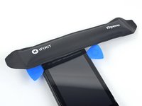
Heat an iOpener and apply it to the bottom edge of the screen for around two minutes to to help soften the adhesive.
-
-
-
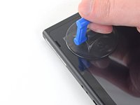
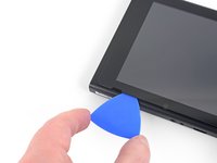
Apply a suction cup to the bottom-left corner of the screen.
-
Pull up on the suction up with strong, steady force to create a gap.
-
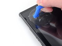
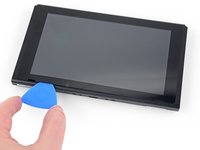
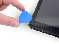
Insert the point of an opening pick into the gap, making sure to only insert the pick about 5 mm.
-
-
-
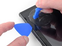
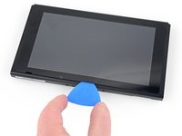
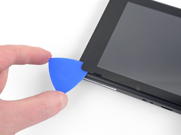
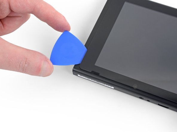
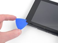
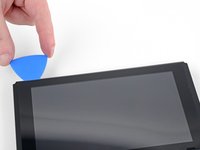
Slide the opening pick along the bottom edge of the screen to slice the adhesive.
-
Leave the pick inserted to prevent the adhesive from re-adhering to the frame.
-
-
-
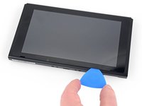
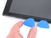
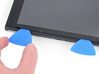
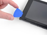
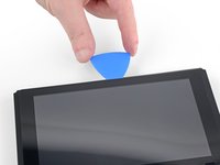
Insert a second opening pick into the gap to the left of the first pick.
-
Slide the opening pick back towards the left side of the device.
-
Leave the opening pick inserted.
-
-
-
Heat the left edge of the screen for around two minutes to help soften the adhesive.
-
-
-
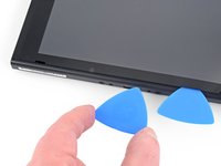
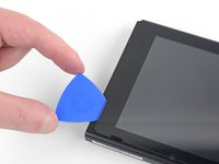
Continue sliding the opening pick around the bottom-left corner to slice the adhesive.
-
-
-
Continue sliding the opening pick along the left edge of the screen to slice to adhesive.
-
-
-
Heat the top edge of the screen for around two minutes to help soften the adhesive.
-
-
-
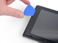
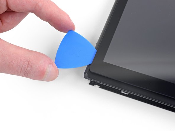
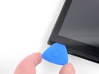
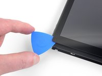
Continue sliding the opening pick around the top-left corner of the screen to slice the adhesive.
-
-
-
Continue sliding the opening pick along the top edge of the screen to slice the adhesive.
-
-
-
Heat the right edge of the screen for around two minutes to help soften the adhesive.
-
Place the flat end of a spudger into the gap along the left edge of the screen.
-
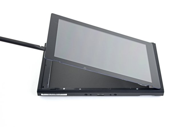
Carefully and slowly lift the left edge of the screen, opening it like a book.
-
-
-
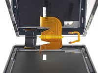
Lift the right edge of the screen straight off the device, threading the ribbon cables through the frame as you do so.
-
-
-
Remove the four screws securing the front frame to the midframe.
-
-
-
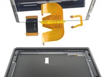
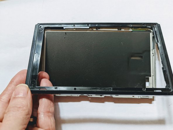
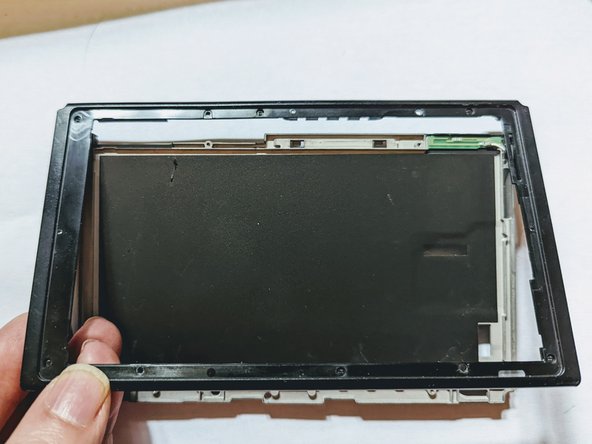
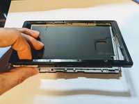
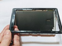
Lift the front edge of the frame then slide the frame up toward the top of the display to remove it.
-
-
-
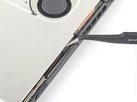
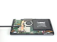
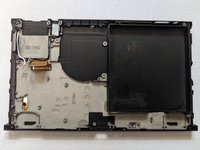
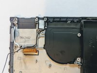
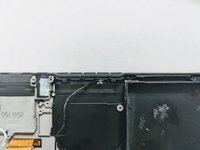
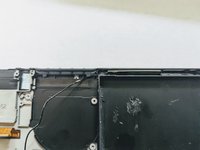
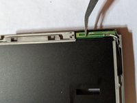
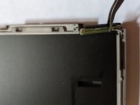
Verify the coax wire is free of any obstructions or routing inside the device.
-
-
-
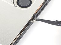
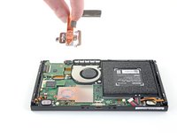
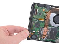
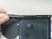
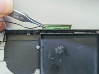
The antenna is held in with light adhesive, so simply grasp it and pull up to release it.
-


To reassemble your device, follow these instructions in reverse order.
Cancel: I did not complete this guide.
4 other people completed this guide.
