Introduction
Follow this guide to replace a damaged or drifting joystick in a right Joy-Con 2 controller. If you need to replace the joystick in a left Joy-Con 2, follow this guide instead.
The Joy-Con 2 uses JIS screws. If you use a non-iFixit Phillips driver in JIS screws, you'll risk stripping them.
What you need
-
-
Use a tri-point Y00 driver to remove the two 3.1 mm‑long black screws on the left edge of the controller.
 Ask FixBot
-
-
-
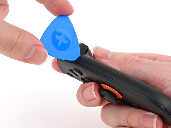
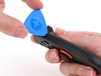
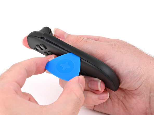
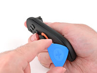
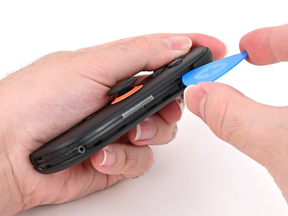
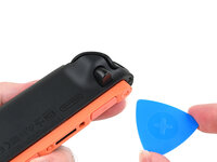
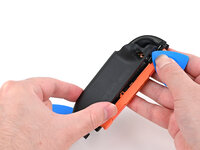
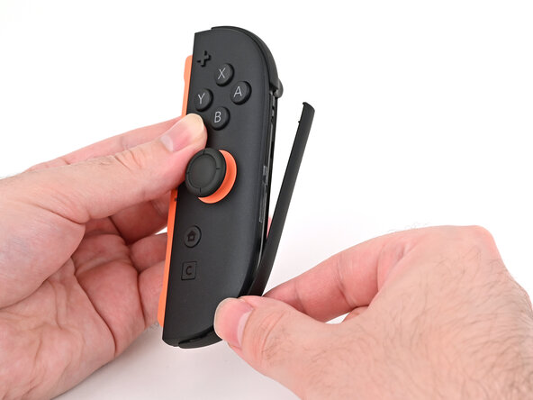
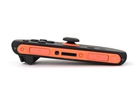
Insert an opening pick into the gap underneath the bumper button on the right side of the controller, with a point of the pick pointing downwards.
-
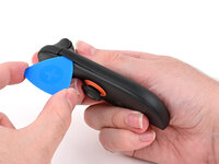
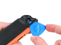
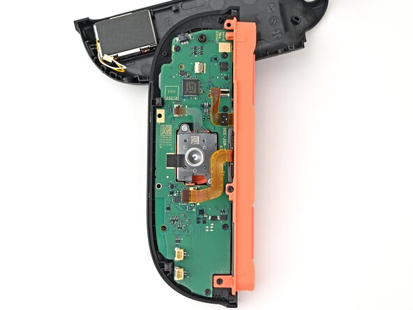
Pry up to slightly lift the plastic strip running across the right edge of the controller.
-
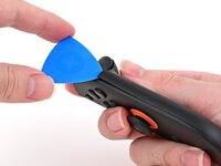
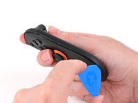
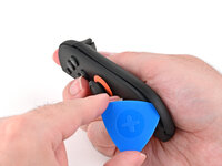
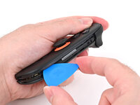
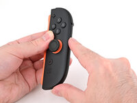
Slide the opening pick around to the front of the controller.
-
-
-
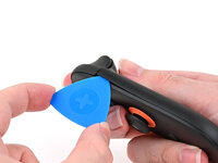
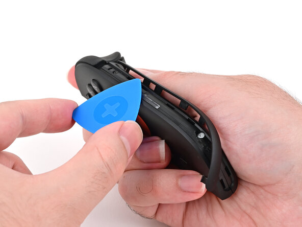
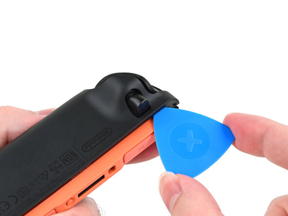
Slide the opening pick down the plastic strip to separate the clips and adhesive securing it to the controller's body.
-
-
-
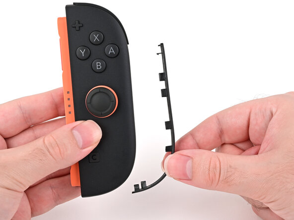
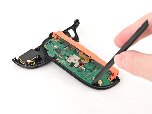
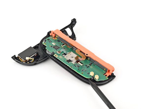
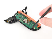
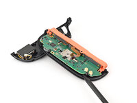
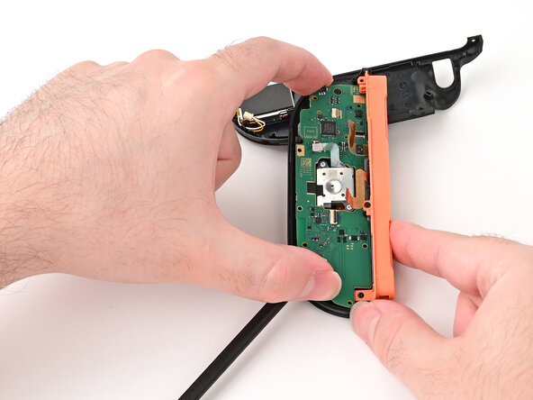
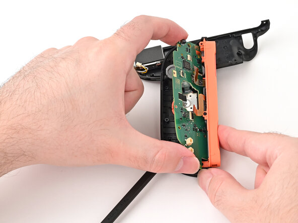
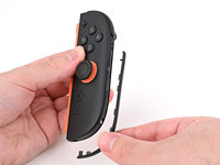
Pry up on the bottom edge of the plastic strip with slow, steady force.
-
Repeat this prying action along the length of the strip until it's fully detached.
-
-
-
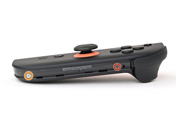
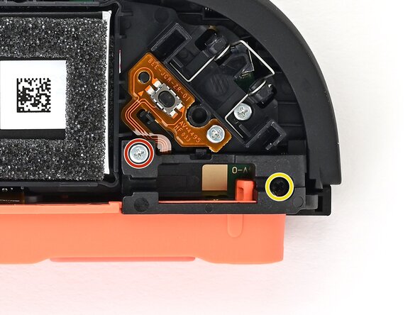
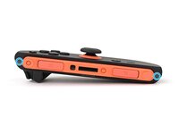
Remove the two screws on the right edge of the controller:
-
One 3.1 mm‑long tri-point Y00 black screw
-
One 3.0 mm‑long JIS 00 silver screw
-
-
-
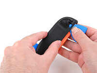
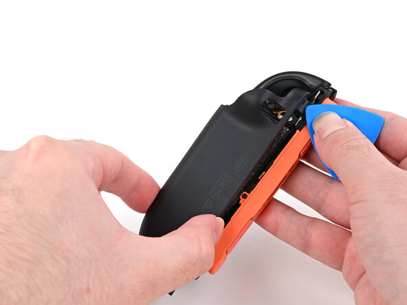
Insert an opening pick into the gap between the front and back halves of the controller on its right side.
-
Slide the pick down the controller to disengage the clips.
-
Leave the opening pick at the bottom of the controller's right edge, just before its curve.
-
-
-
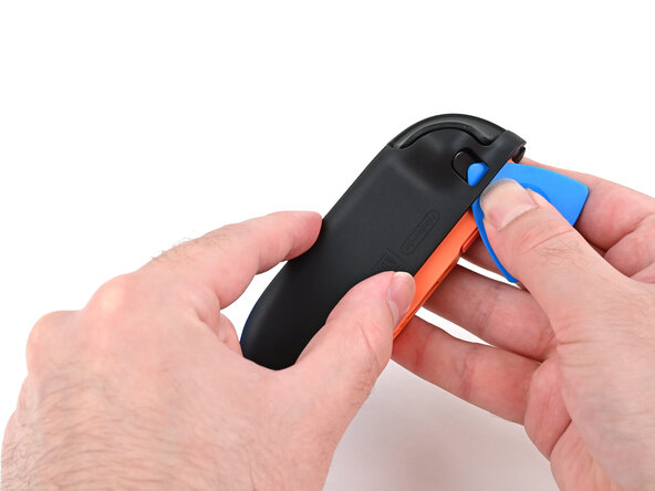
Hold the controller upside-down.
-
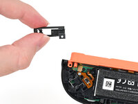
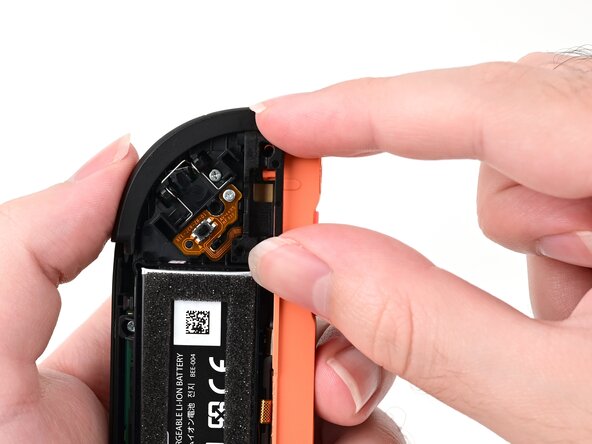
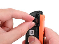
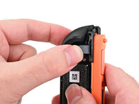
Insert a point of another opening pick next to the release button towards the top of the controller.
-
Use the opening pick to press the release button through the gap.
-
-
-
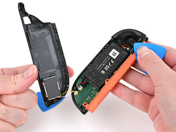
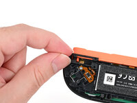
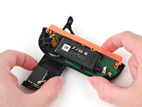
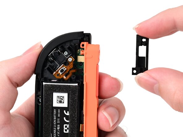
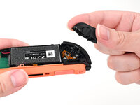
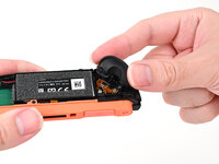
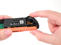
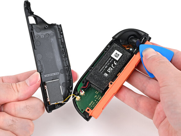
While holding the release button with the opening pick, use your other hand to slide the back cover down to release the clips securing it to the controller's body.
-
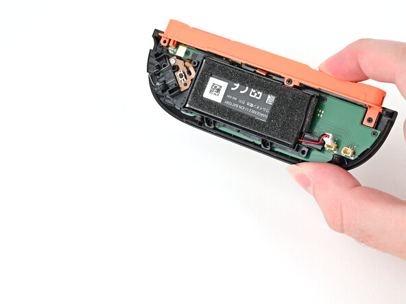
Open the back cover.
-
-
-
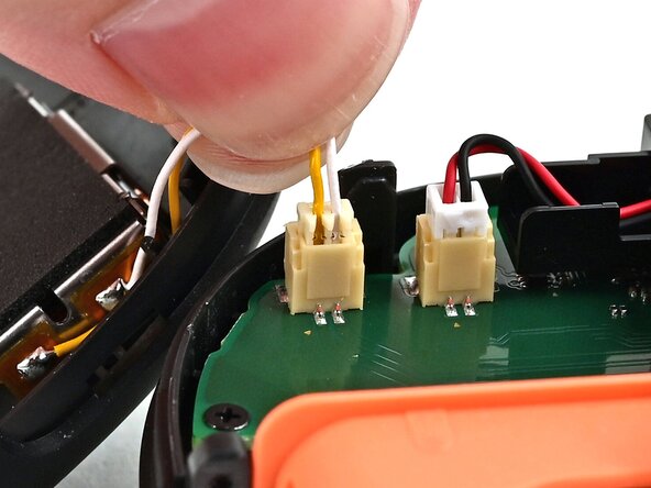
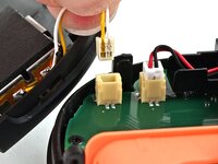
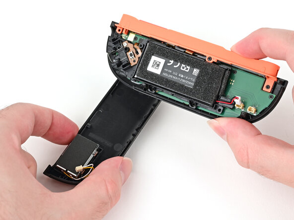
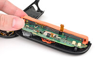
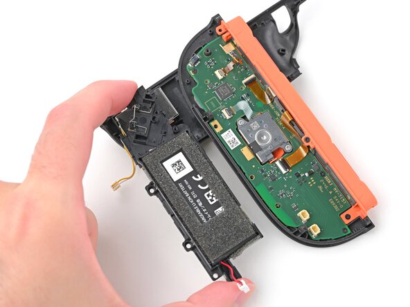
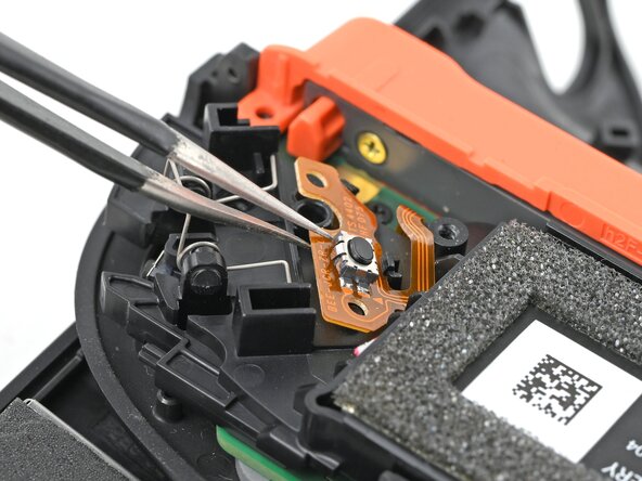
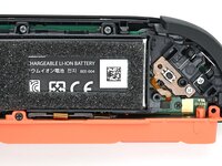
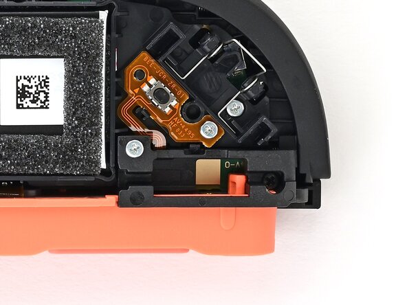
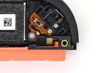
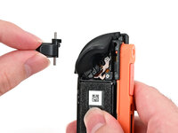
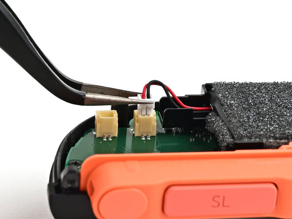
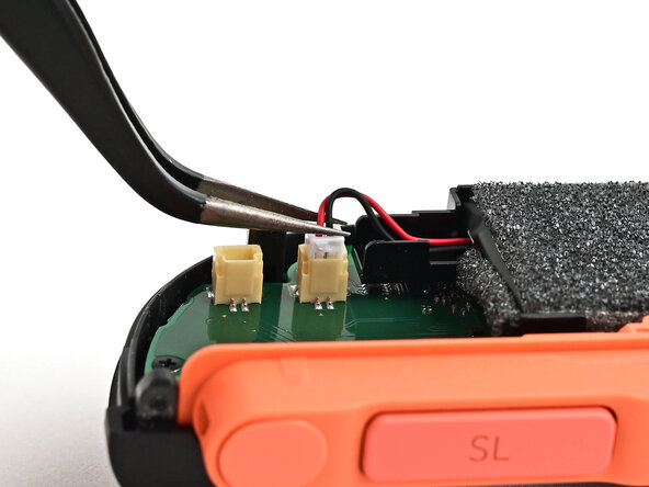
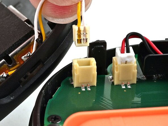
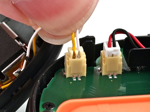
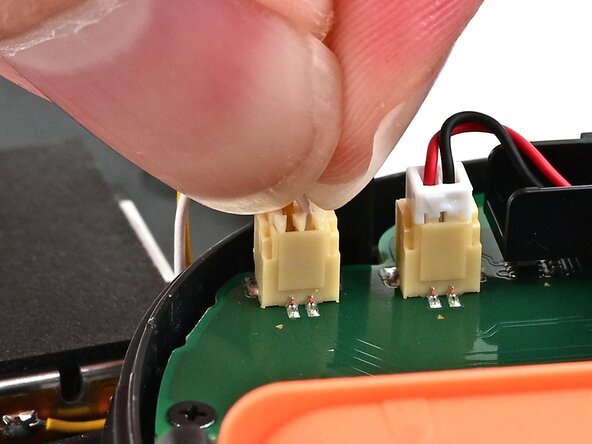
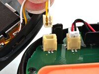
Firmly grasp the two wires (yellow and white) above the rumble motor connector, located at the bottom of the controller's board, and pull the beige connector out of its socket.
-
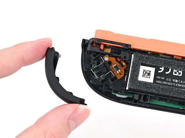
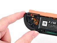
Remove the back cover.
-
-
-
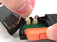
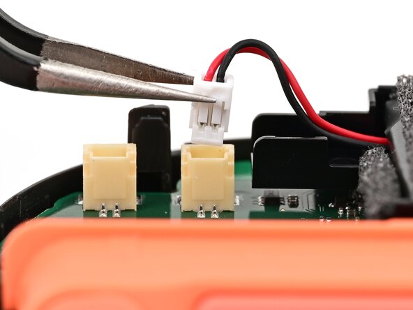
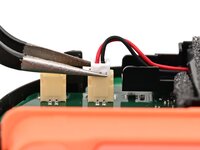
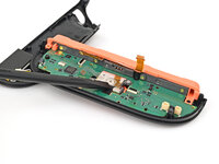
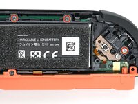
Use tweezers or your fingers to firmly grip the battery cable's white JST connector and pull straight away from its socket to disconnect it.
-
-
-
Insert an opening pick between the bumper (R) and trigger (ZR) buttons at the top of the controller.
-
Use the opening pick to pry the trigger away from the bumper until it pops off the controller.
-
-
-
Use a JIS 00 driver to remove the five screws securing the midframe:
-
Four 3.9 mm‑long silver screws
-
One 6.2 mm‑long black screw
-
-
-
Hold the midframe lightly in place.
-
Pull the bumper (R) button off its mounting pegs and remove it.
-
-
-
Pick up the release button mounting bracket and remove it.
-
-
-
Use the back cover to prop up the controller while you work.
-
-
-
Use a JIS 00 driver to remove the 3.9 mm‑long silver screw securing the trigger button board.
-
-
-
-
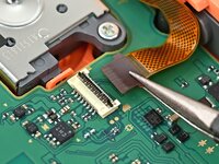
Insert the point of a spudger underneath the board, and lift it until it pops up.
-
-
-
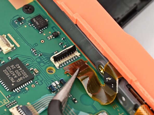
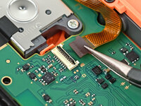
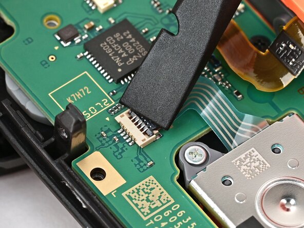
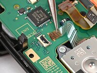
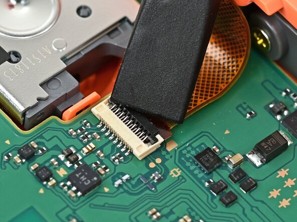
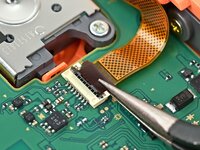
Use the point of a spudger to flip up the locking flap on the trigger button ZIF connector, located on the controller's board.
-
-
-
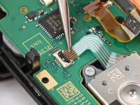
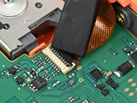
Use tweezers or your fingers to gently pull the cable out of its socket.
-
Remove the trigger button board.
-
-
-
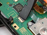
Repeat this procedure to disconnect the remaining three ZIF connectors on the controller's board.
-
-
-
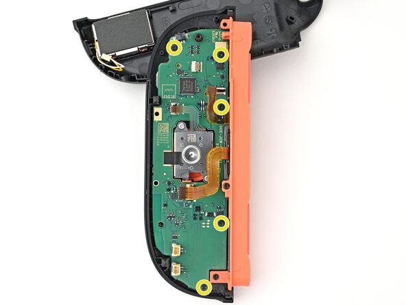
Use a JIS 00 driver to remove the five 3.1 mm‑long black screws securing the board to the controller.
-
-
-
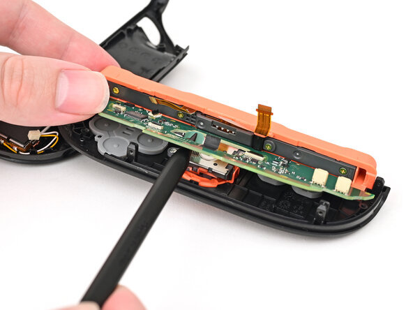
Insert the point of a spudger between the board and the controller, near the battery connector socket.
-
Pry up on the board enough to grasp its edge with your fingertips.
-
-
-
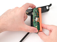
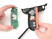
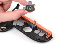
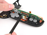
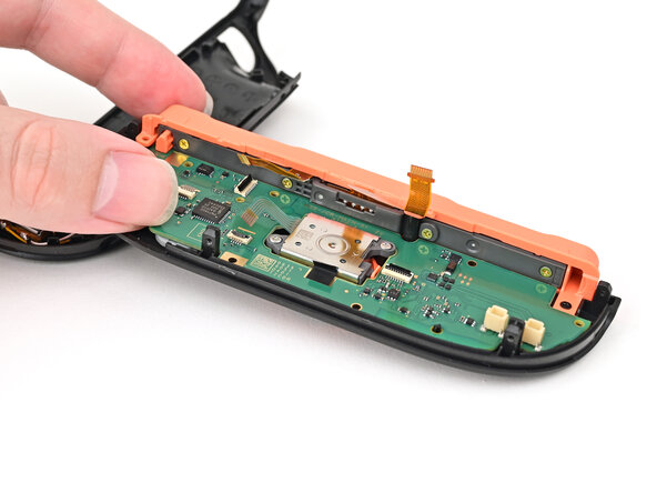
Lift the board by its outer edges to a roughly 45-degree angle, so it's no longer being blocked by the joystick assembly.
-
Remove the board.
-
-
-
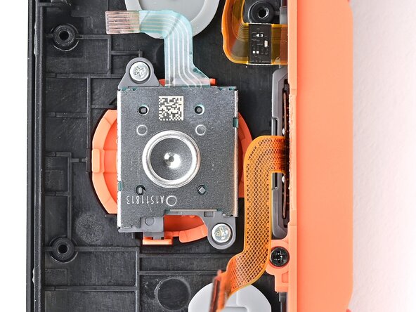
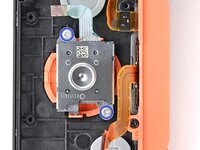
Use a JIS 00 driver to remove the two 3.9 mm‑long silver screws securing the joystick.
-
-
-
Congratulations on completing disassembly! The remaining steps will show how to reassemble your console.
-
-
-
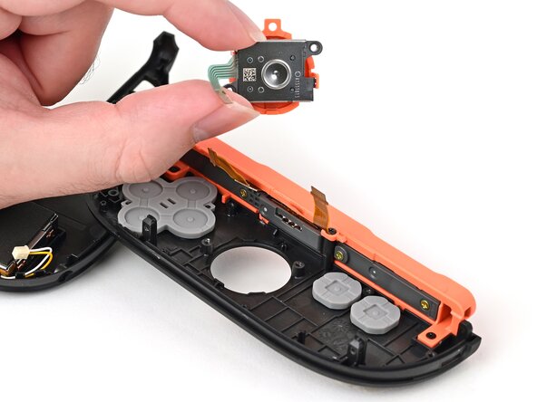
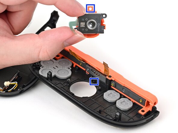
Align the cut-out in the joystick's plastic frame with its peg on the controller.
-
Set the joystick in the controller. Gently wiggle the joystick to ensure it's fully seated.
-
-
-
Use a JIS 00 driver to install the two 3.9 mm‑long silver screws securing the joystick.
-
-
-
Lower the board's flat side into the controller at an angle.
-
Use a spudger to bend the joystick's ribbon cable so it's perpendicular with the joystick.
-
Lower the board so the joystick's ribbon cable routes through the joystick cut-out in the board. Ensure the board is sitting underneath the locking tab on the frame.
-
-
-
Push the board towards the controller's inner edge (the side with the shoulder buttons) to prevent it from colliding with the joystick module.
-
Lower the board into the frame.
-
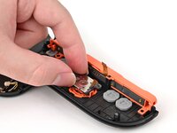
Use your finger or the flat end of a spudger to press the black tape onto the back of the joystick module.
-
-
-
Use a JIS 00 driver to install the five 3.1 mm‑long black screws securing the board to the controller.
-
-
-
Make sure the locking flap is flipped up on the joystick cable ZIF connector.
-
Insert the joystick ribbon cable into its ZIF connector until it's fully seated.
-
Use your finger or a spudger to flip the locking flap down to secure the cable.
-
-
-
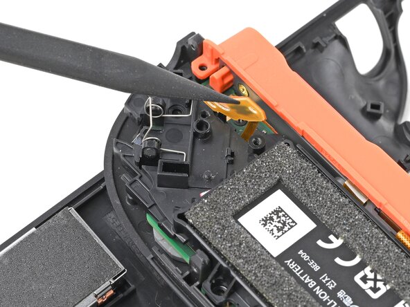
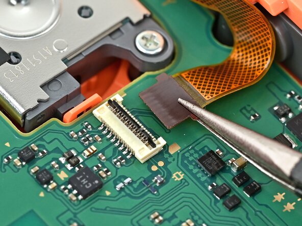
Make sure the locking flap is flipped up on the Joy-Con connector cable ZIF connector.
-
Insert the Joy-Con connector ribbon cable into its ZIF connector until it's fully seated.
-
Use your finger or a spudger to flip the locking flap down to secure the cable.
-
-
-
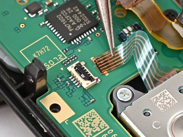
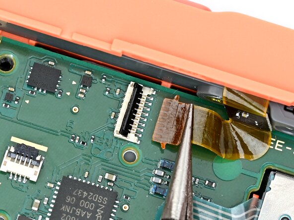
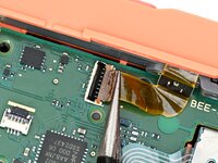
Repeat this procedure for the shoulder button ZIF connector. The cable is fully seated when its brown "wings" are in their slots on both sides of the connector.
-
-
-
Make sure the locking flap is flipped up on the trigger cable's ZIF connector.
-
Position the trigger button board so its ribbon cable is aligned with its ZIF connector on the board.
-
Use tweezers or your fingers to gently slide the ribbon cable into its ZIF connector.
-
Flip the locking flap down to secure the cable.
-
-
-
Align the midframe with its screw holes on the outer edge of the controller and set it into place.
-
-
-
Use tweezers or your fingers to set the bottom edge of the trigger button board underneath its tab on the midframe.
-
Press the board into place so the black peg on the midframe protrudes through the hole on the bottom corner of the board.
-
-
-
Use a JIS 00 driver to install the 3.9 mm‑long silver screw securing the trigger button board.
-
-
-
Align the two springs on the bumper with their two posts on the midframe, and press it into place.
-
-
-
Use a JIS 00 driver to install the three 3.9 mm‑long silver screws securing the midframe.
-
-
-
Align the release button mounting bracket with its screw holes and press it in the frame so it snaps into place.
-
-
-
Use a JIS 00 driver to install the two screws securing the release button bracket.
-
One 3.9 mm‑long silver screw
-
One 6.2 mm‑long black screw
-
-
-
Align the trigger button with the top of the controller, with the "ZR" engraving facing out.
-
Set the trigger button onto its metal spring. Ensure the legs of the spring are seated properly in their channels on the midframe.
-
Press firmly on the trigger button to snap it into place.
-
-
-
Hold the release button so its smooth face is perpendicular to the controller.
-
Insert the release button into its bracket.
-
-
-
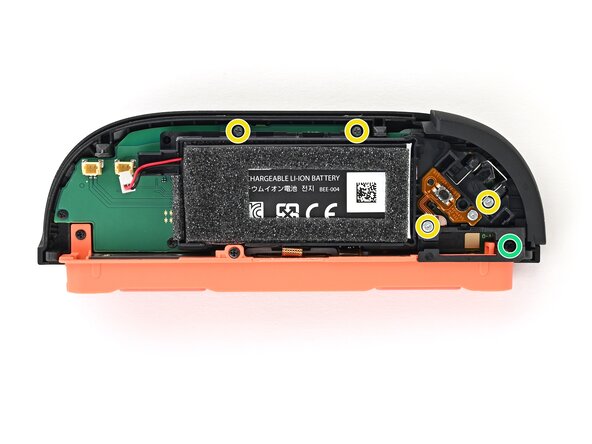
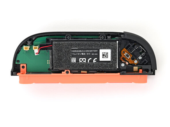
Align the battery connector with its socket on the board.
-
Press down on the connector until it's fully seated.
-
-
-
Align the rumble motor connector to its socket on the bottom edge of the board, and push down until it's fully seated to connect it.
-
-
-
Use an opening pick to press and hold the release button.
-
Place the back cover over the controller body so the release button cutout is slightly below the release button.
-
Press and slide the back cover up until the cut-out for the release button is aligned with the button itself.
-
-
-
Install the two screws on the right edge of the controller:
-
One 3.1 mm‑long tri-point Y00 black screw
-
One 3.0 mm‑long JIS 00 silver screw
-
-
-
Align the clips on the plastic strip with their cut-outs on the right edge of the controller body.
-
Insert the clips on the bottom edge first, then insert the rest so the plastic strip sits flush.
-
-
-
Use a tri-point Y00 driver to install the two 3.1 mm‑long black screws on the left edge of the controller.
-


You finished fixing your Joy-Con 2!
Take your e-waste to an R2 or e-Stewards certified recycler.
Repair didn’t go as planned? Try some basic troubleshooting, or ask our Joy-Con 2 Answers Community for help.
Cancel: I did not complete this guide.
10 other people completed this guide.

3 Guide Comments
Hello Reader!
I recently broke my right Nintendo Switch 2 joy-con when it fell off of my bed, and the joystick stem just snapped completely off. I thought all hope was lost, but then I found this guide and bought a repair kit (with proper screwdrivers, pliers, sticks, and smudger; can literally get it off of Amazon, if not from this website).
The steps were super thorough, and the pictures were amazingly accurate. I am a 19-year-old with no mechanical or technological experience, yet I was able to completely repair my joy-con in around an hour (maybe less), and now I don't have to buy new ones!
Please follow this guide if you need to fix your joy-con!! It works!!
My daughter drop her switch 2 and broke right side joy stick red The guide was amazing, the disassemble process and reassemble easy.. fyi make sure the led tab on step 37 can be a pain, I recommend that you reconnect the battery before going any further if not you will have to take the hole assembly apart again if that cable is not properly seated..