Introduction
修理人は電子部品や電気回路をテストできるマルチメーターの使用方法を知っておく必要があります。マルチメーターの最も基本的な機能を知るために、ぜひ参照ください。
電流や静電容量の計測のような、より高度な計測をマルチメーターで行う方法については、こちらのガイドを参照して下さい。
What you need
-
-
通電テストは2つのものが電気で繋がっているかどうかを確認するためのものです。もし何か動いているならば、電流は双方間で問題なく流れています。
-
通電しない場合は、回線がどこかで切れています。疲弊したヒューズや不十分な半田付け、または正しくワイヤーが付けられていない回線がある可能性があります。
-
-
-
マルチメーターの COM端子に黒色のテストリードを差し込みます。
-
赤色のテストリードを Vと書いてある方の端子(画像のマルチメーターの場合は右側の端子)に差し込みます。
Why do we need to make sure that no current is running through the circuit?
When there is another parallel branch with 24VDC power and 4-20mA output, the value of the resistance measured comes as zero. Whats the reason?
The way that a meter measures resistance is by sending a small current across the probes and then measuring the resulting voltage. So, another current will disturb your digital multimeter's (DMM) reading.
nicO -
-
-
-
マルチメーターの電源を入れて、ダイアルを導通モードに設定します。(音波のように見えるアイコンで表示されます)
I want to search the resistance of gold and see if I have some
What does a sound wave look like?
Gold is highly conductive near zero resistance which is why they use it in conducters. Use "specific gravity" type tests or "mass spectromatry" type tests for elements.
Sound looks like sine waves with various amplitudes and cycles per unit of time.
-
-
-
-
ダイアルを抵抗値測定モードに回します。
-
測定範囲を手動で設定するタイプのマルチメーターを使っている場合は、一番低い範囲の抵抗値を測るように設定して下さい。
-
-
-
このモードでは、マルチメーターは1つのプローブに少しの電流を送り、もう一方のプローブで何を(何かあれば)受信しているか計測します。
-
導通サーキットもしくは相互コンタクトでもプローブが接続されているならば、テスト電流は流れています。スクリーンでは0(もしくは限りなく0に近い値、0.8)の数値を指します。非常に低い抵抗があるということは言い換えれば電流が流れていると示します。
-
電流が探知できない場合は電流が流れていません。スクリーンでは1かOL(オープンループ)を指します。
It means you have current flowing which would indicate a good path or circuit. Also means you have a power supply connected which I think was mentioned earlier in the article to disconnect all power supplied, as in a.c., d.c. Especially in a vehicle as running tests on computer module circuits with the vehicle battery connected can damage a computer module circuit..
I'm very pleased to have discovered these directions. Interestingly, I tried the two probes on different sections of a screwdriver – resistance showed very high. Is that possibly because of chrome coating on the screwdriver?
May not be a chrome coating at all even if it looks like it. The screw drivers "resistence" is the result of what alloys are used in the shank of the screw driver ... ie ... tin, zinc, carbon, etc.
-
-
-
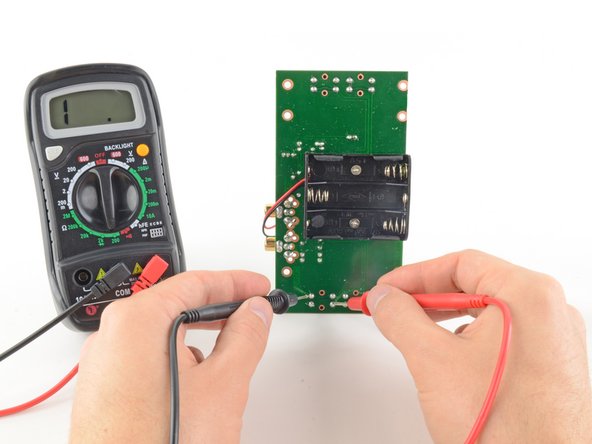
通電テストを完了するには、テストする回路またはコンポーネントの両端にテストリードを一つずつ接続します。
-
前途のように、回路が閉じる時、画面には0(もしくは0に近い数字)が表示されます。
-
画面に1またはOL(open loop)が表示されている場合は、回路が閉じていません。つまり、あるテストリードから別のテストリードに電流が流れる経路がありません。
What does it mean when I first get 1 then the meter jumps to all kinds of numbers and there is no beeping?
Most likely you have bad contact with whatever you are measuring.
-
-
-
黒いテストリードを COM ポートに挿入して下さい。
-
赤いテストリードを Vと書かれているポート(画像のマルチメーターの場合は右側のポート)に挿入して下さい。
-
-
-
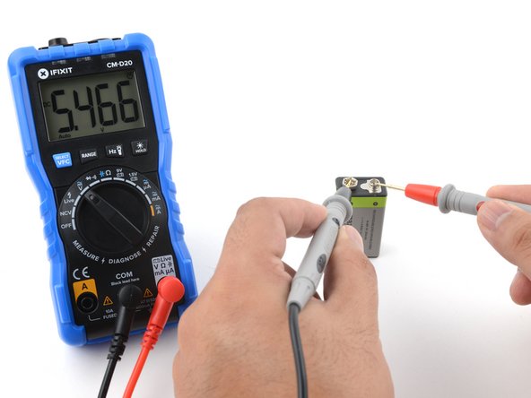
赤のプロープを+電極に当て、黒のプロープを-電極に当ててください。マルチメーターは測定した電圧値を表示するはずです。
-
次の手順は飛ばして下さい。手動で測定範囲を設定しなければいけないマルチメーターを使った電圧計測の手順を説明しています。
-
-
-
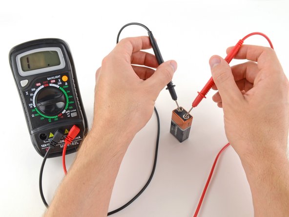
赤のプロープを+電極に当て、黒のプロープを-電極に当ててください。
-
もしレンジが高すぎる場合、正しい数値を読み取ることができないかもしれません。この例ではマルチメーターは9Vを指しています。これでも良いですが、より低いレンジの方がより読み取りやすくなるでしょう。
-
もしレンジが低すぎる場合、マルチメーターは1かOLの表示をします。これは電圧が過剰であるか計測範囲から外れています。これはマルチメーターを傷つけるものではありませんが、より高いレンジにダイアルを合わせるべきです。
-
-
-
まず、測定したい回路や部品に電流が流れていないことを確認します。電源を切り、電源プラグをコンセントから抜き、電池を取り外してください。
-
黒のプロープを、マルチメーターのCOMポートに挿してください。
-
赤いプローブをΩ記号のとラベル表記されたポート(この場合は右ポート)に差し込みます。
Be careful when testing ohms on the circuit board, the best test is to remove the part so you are only testing the part not the circuit around the part. Transistors, resistors, caps need to be removed or at best one leg of the part. One time I had a burn open resistor, then I tested the resistor with my Ohms test I got some resistor reading. This was caused by back feed in the circuit.
-


Cancel: I did not complete this guide.
1004 other people completed this guide.
Special thanks to these translators:
100%

These translators are helping us fix the world! Want to contribute?
Start translating ›


132 Comments
EASy and helpful indeed
Iwant to know hw to test caperstas
Thank you. Very easy and good training
Very helpful for beginners, thanks for these clear instructions!
great article. thanks
thank you !!! for this info!!!
Thanks a lot this is very clear and helpful!
Thanks Jeff. I just purchased a cheap mm. All instructions were in Chinese. Your help made sense of it all, so easy.
Iwant to knw hw to test power suply
Brilliant thank you
It truly does.
so nice Bro...Thanks a lot...
Thanks a lot
Love the resources on the Pro site.
Very good instructions
Nice guide.pl add some additional examples to have better understanding for beginners.Thank you
Nice guide. Pl add some additional practical examples. Thank you.
I'm doing exactly this and mine won't read any voltages, but it will read resistance. I've tested it with multiple batteries that I know work, but I only get a read of 0. What might be the problem?
Thank you, Haven't used one of these is ages; this was a great refresher!
thanks for a very easy tutorial, it is very helpful!
The basics. Soooo important. Well done, short and concise.
Most helpful thank you!
Had multimeter for a couple years, never knew how to make it beep!
Thank you for these great instructions. The instructions that came with the multimeter were not helpful for a beginner, and these really helped us diagnose our problem.
Thank you for the great instructions. My question and the reason for my looking online for info on using a multimeter was to find out what the various resistance readings mean on a digital tester. I am checking out a defrosting element in my refrigerator and got a reading of 12 or 15 ohms. The information I was reading said a 15-100 ohms meant the element was OK, another book said if medium resistance was found it was OK.
By going online I was looking for the answer as to what is low, medium and/or high resistance ranges are.
I did enjoy your instructions, they were easy to understand.
I have used a meter for a long time. Never had instructions so clear and easy to follow. Thank you very much.
The pictures are also very clear and helpful.
Beautifully put. I truly appreciate the lesson. I've learned something of impirtance. Thank you.
it really useful for begginer
Thanks you for the lesson :)
Hi,
das ist wirklich sehr anschaulich aufgebaut und benutzerfreundlich, vielen Dank dafür!
Wer jetzt noch genau wissen möchte wie Multimeter funktionieren und worauf Sie beim Kauf achten sollte der kann gerne noch auf https://multimeter-tester.de schauen und weiter lesen.
Ich wünsche euch noch einen schönen Abend und einen bestmöglichen Start ins neue Jahr.
LG
Thanks you for the lesson :)
Thanks and had help me a lot
Had help me a lot. Many Thanks
Thanks , sometimes need too refresh with the basics.
Very informative! Easy to understand.
Well written.
Simple and easy thanks
I have been searching a tutorial on getting started with trouble shooting an automotive parasitic draw. I have no background in different types of functions of a mmeter such as continuity, voltage, and resistance, your tutorial was a must have. It gave me an understanding of just the basic terminology of the more advanced tutorials. I give it a major thumbs up, excellent tutorial thanks a million !!!!!!
Thank you. This was very helpful to me. Very clear and easy to understand....
Thanks for supportive/useful post
Very Helpful.,thanks
Excellent please give us more of the same, primarily to help with understanding of the subject matter at a basic level.
Excellent and elegantly simple guide.
Thanks you so much for this.For me as a beginner,I didn't find difficulties in reading this but its fruitful one.
thanks a million
It was just awsome.Before your tutorial it just was looked like some alien device to me and now I think it's having very simple working principle. I am now pretty confident to work with it. A very big thanks.
Awesome thanks.. I knew you could use this for a lot of things but not this much.
I have a problem with my multimeter (Mastech MY74), the first thing I did was stupid, haven't read the user manual and tried it on a live socket and now it doesn't want to work. I have changed the fuses (600V, 0,4A and 10A), but it still doesn't work. Does anyone have an idea what else could have went wrong and how to test it?
Best regards
Very useful. I liked the statements like ‘this will not harm the multimeter but will show negative reading ‘. For non science folks like me, these questions crop up often so this guide takes away the anxieties.
Nice article with great illustrations.
Apart from measuring DC voltage, resistance and continuity, they can also measure AC voltage, DC current, transistor and Diode checking, which I learnt from here https://circuitdigest.com/article/how-to...
Following the KISS method of instruction!
Very well done!
marvellous explanation for a layman good luck& thanks
Excellent guide. Very well explained and easy to use.
Dead easy. Very impressed.
Thanks a lot. :) My fear with multimeter is gone now. I am able to measure with confidence.
Jeff, thanks for your step by step multimeter guide. I have also written https://bestmultimeterreviews.org/ similar article in my blog. But, your article is much better than me.
Simple, easy to understand, well presented. Very helpful thanks.
Tanks very much….Its really
Thank you. Very clear and thorough.
Very helpful :) Thank you.
Helpful thanks
Cool keep up the good work and thanks
thanks for a very easy tutorial, it is very helpful! pl add some additional examples to have better understanding for beginners.Thank you
sateesh
Thank u for the precise description,very very useful for beginners.
A MAZUMDER
thanku for guide!!!
I studied multimeter in my 11th grade and since then, haven’t been around these things for a long time! I was glad to go through the above instructions and as my nephew has been studying physics as well, I was able to guide him through some subjects which really gave me a good day and made my nephew happy. Thanks a lot.
Very good explained well. Thank you.
Exceptional directions and explanations for each step. Even an inexperienced user (such as myself) can understand and follow the instructions. So hard to find such detailed instructions for those that “want to be in the know”!! Kudos! You deserve 4+ Stars :)
We thank you for the information
I was always confused about electricity and how to test it but your instructions have given me a better understanding of it. I now have a place to go to for future reference. Thanks.
thanks for the lucid description of the three phases of testing an electronic item; good job!
An excellent guide. Thank you.
Thanks, that's helpful to me
Congrats for showing us the best way use it
Excellent guide Thank you!!!!
Well. .. thank you, this is awesome
thank you very much
Well done. You've explained it in detail and was completely understandable. Tm
Good Content …………..Easy to Learn!
When testing a Tweeter the multimeter reads OL on the resistance scale. What does this mean?
Really helpful
Very simple and easy to understand. Thank you very much for your help, now I can use a multimeter now.
Very informative ; Thank you ?
Thank you so much for making it so simple to follow. Because before I new what I was doing I got the all wires mixed up on my car battery. And I nearly melted my fingers to the wires. So thanks again c foley… craigfol659@gmail.com
Very good explained! Thanks.
easy to understand
Thanks for teaching me
Thanks very helpful
Thanks. Very Helpful
Thank you so much easy and healpful
Thank you! Great how to advice for a beginner!
Thanks for the very detailed guide, good content and quality pictures.
AC is not dangerous, even V's aren't. Everyone must get worried about A's.
Sadly, you didn't include how to measure A (amperage or current), which always causes troubles to measure, to learn and understand.
Hi how can I test a signal transmission through an ffc or fpc cable using a multimeter
That was a really clear and concise tutorial. Thanks.
Just one request. Could you do ones on other capabilities of a DMM, please? For example, measuring ampage, testing doids and LEDs.
Cheers Wal