Introduction
I bought this keyboard off eBay broken just to tear it down for posterity. I found very little that could be repaired on it. But you get to see its guts. This teardown destroys the keyboard!
What you need
-
-
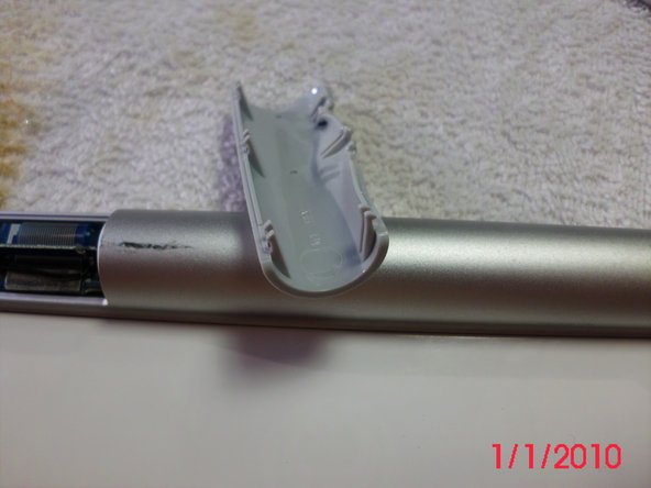
To open the battery compartment, on the left side of the keyboard use a coin to loosen the screw off cover.
-
The keyboard's power button is on the right side
-
-
-
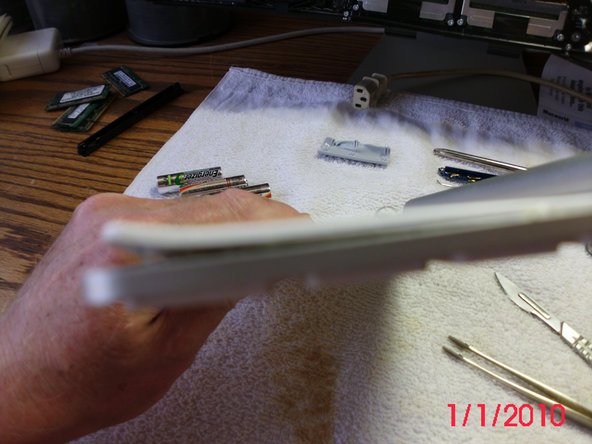
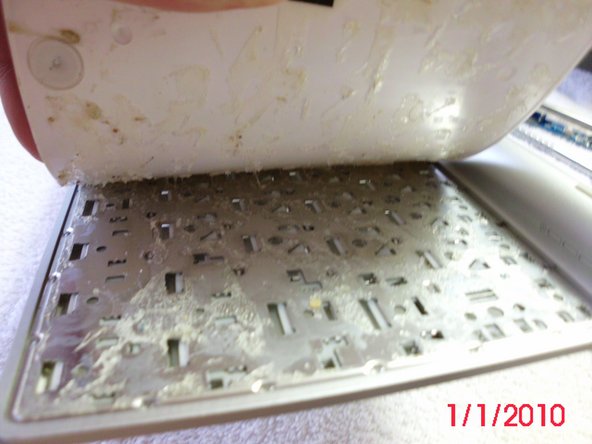
The plastic is very stiff and there are three sets of two hooks on each side. This one has been deformed on the back right hand side from a heat gun.
-
There is a 90 mm by 12 mm circuit board intersected by a vertical 53 mm by 7 mm board forming a T shape. The vertical board appears to be the bluetooth antenna.
-
Part # 820-2181 is printed on the board.
-
This board also has the Power Indicating LED light. This board fits inside the round casing unit by the power button. The power button, battery connector and keyboard all connect to this board.
-
-
-
The board is held in place with a small Phillips screw.
-
Ater removing the screw the board can be gently extricated from the tube. The white plastic disc to the right of the screw needs to be pushed to the right to free up the board.
-
Note the red and black wires. This connector inserts laterally. The wires go to the battery receptor in the middle of the tube.
-
The screw is in two parts, a phillips screw goes into a post screw. The top screw holds in the board and the post screw holds the On/Off switch in place.
-
-
-
-
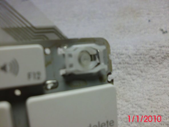
Here you can see the pole that the screw went in. You can remove this, which allows you to remove the power button and the white housing.
-
Also, here is the battery terminal (spring loaded) which had to be forced out. It's held in the tube by the expansion ring, which unfortunately is the best-made bit of this keyboard. I forced it out using a long screw driver, but unfortunately broke the wires. Keyboard had died anyway, thanks Apple.
-


Team

25 Comments
This keyboard holds 3 AA batteries not 2.
No quibble at all. My keyboard ca. 2010 years old is two batteries. No question but that the A1255 had three, the A1314 which I have is two. Duh! (for me). I didn't think initially about model numbers and I got enough out of this to make it work
Thanks to this post I managed to remove a stuck battery on an A1314, pushing the battery out with a letter opener.
The ribbon cable is not hard to remove, but a little trick to open and relock it back? I just had cataract surgery which didn't help, but it's pretty obvious when you take a close look.
There was no corrosion; the keyboard was working. Someone installed off-brand batteries, no leaks just stuck. New name brand (copper tops) slide in and out without a problem.
jmc56 -
If you kept the keys, I'd like to buy an "L" key and the plastic/rubber part that goes underneath. Little accident with my keyboard left L key inoperable .... ;-)
Kevin
]can I buy new buttons, the up arrow fell off ?
How did you manage to knock out the battery terminal with only a screwdriver and from which end of the aluminum encasement did you knock it out?