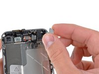
iPhone 4 Power & Sensor Cable Replacement

What you need

  1. iPhone 4 Power & Sensor Cable Replacement, Rear Panel: step 1, image 1 of 2 iPhone 4 Power & Sensor Cable Replacement, Rear Panel: step 1, image 2 of 2
    • Before you begin, discharge your iPhone battery below 25%. A charged lithium-ion battery can catch fire and/or explode if accidentally punctured.

    • Power off your iPhone before beginning disassembly.

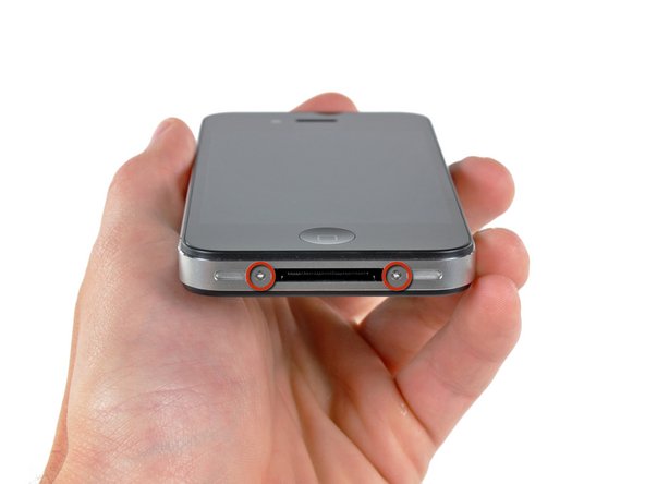
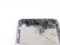
    • Your iPhone 4 rear cover may have either two #000 Phillips screws or Apple's 5-Point "Pentalobe" screws (second image). Check which screws you have, and ensure you also have the correct screwdriver in order to remove them.

    • Remove the two 3.6 mm Pentalobe or Phillips #000 screws next to the dock connector.

    • Be sure the driver is well seated when removing Pentalobe screws, they are very easy to strip.

  2. iPhone 4 Power & Sensor Cable Replacement: step 2, image 1 of 2 iPhone 4 Power & Sensor Cable Replacement: step 2, image 2 of 2
    • Push the rear panel toward the top edge of the iPhone.

    • The panel will move about 2 mm.

  3. iPhone 4 Power & Sensor Cable Replacement: step 3, image 1 of 1
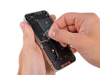
    • Pinch the rear panel with your fingers and lift it away from the iPhone. Alternatively, use a Small Suction Cup .

    • Be careful not to damage the plastic clips attached to the rear panel.

    • If you are installing a new rear panel, be sure to remove the plastic protective sticker from the inside of the camera lens and the sticker from the large black area near the lens.

  4. iPhone 4 Power & Sensor Cable Replacement, Battery: step 4, image 1 of 1
    • Remove the single 2.5 mm Phillips screw securing the battery connector to the logic board.

    • Some devices may have two screws, one of which holds down the contact pad which is located above the screw indicated in red in the photo.

  5. iPhone 4 Power & Sensor Cable Replacement: step 5, image 1 of 1
    • Use a plastic opening tool to gently pry the battery connector up from its socket on the logic board.

    • Pry from the top and bottom of the connector bracket—there isn't as much of an overhang on the sides, and you may damage the connector.

    • Be very careful to only pry up on the battery connector and not the socket on the logic board. If you pry up on the logic board socket, you may break it entirely.

    • Remove the metal clip covering the antenna connector.

  6. iPhone 4 Power & Sensor Cable Replacement: step 6, image 1 of 3 iPhone 4 Power & Sensor Cable Replacement: step 6, image 2 of 3 iPhone 4 Power & Sensor Cable Replacement: step 6, image 3 of 3
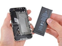
    • Use the clear plastic pull tab to gently lift the battery out of the iPhone.

    • If the tab breaks before the battery is freed, apply a few drops of high concentration (over 90%) isopropyl alcohol under the edge of the battery. Wait about one minute for the alcohol solution to weaken the adhesive. Carefully slide a spudger under the battery tab to release the adhesive.

    • Prying in other places may cause damage. Don't try to forcefully lever the battery out. If needed, apply a few more drops of alcohol to further weaken the adhesive. Never deform or puncture the battery with your pry tool.

    • If there's any alcohol solution remaining in the phone, carefully wipe it off or allow it to air dry before installing your new battery.

    • If your replacement battery came in a plastic sleeve, remove it before installation by pulling it away from the the ribbon cable.

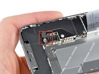
    • Before reconnecting the battery connector, be sure the contact clip (shown in red) is properly positioned next to the battery connector.

    • Before reassembly, clean metal-to-metal contact points with a de-greaser such as windex. The oils from your fingers have the potential to cause wireless interference issues.

    • Perform a hard reset after reassembly. This can prevent several issues and simplify troubleshooting.

  7. iPhone 4 Power & Sensor Cable Replacement, Logic Board: step 7, image 1 of 2 iPhone 4 Power & Sensor Cable Replacement, Logic Board: step 7, image 2 of 2
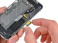
    • Use a SIM card eject tool or a paperclip to eject the SIM card and its holder.

    • This may require a significant amount of force.

    • Remove the SIM card and its holder.

  8. iPhone 4 Power & Sensor Cable Replacement: step 8, image 1 of 2 iPhone 4 Power & Sensor Cable Replacement: step 8, image 2 of 2
    • Remove the following two screws:

    • One 1.2 mm Phillips

    • One 1.6 mm Phillips

    • Remove the thin steel dock connector cable cover from the iPhone.

    • Before reassembly, be sure to clean all metal-to-metal contact points on the dock connector cable cover with a de-greaser such as windex. The oils on your fingers have the potential to cause wireless interference issues.

  9. iPhone 4 Power & Sensor Cable Replacement: step 9, image 1 of 2 iPhone 4 Power & Sensor Cable Replacement: step 9, image 2 of 2
    • Use an iPod opening tool to gently pry the dock cable connector up off the logic board from both short ends of the connector.

  10. iPhone 4 Power & Sensor Cable Replacement: step 10, image 1 of 2 iPhone 4 Power & Sensor Cable Replacement: step 10, image 2 of 2
    • Carefully peel the dock ribbon cable off the logic board and the lower speaker enclosure.

    • Do not use excessive force to peel the dock ribbon cable off the logic board. Doing so may tear the cable.

  11. iPhone 4 Power & Sensor Cable Replacement: step 11, image 1 of 1
    • Use a plastic opening tool to pry the lower antenna connector up off its socket on the logic board.

  12. iPhone 4 Power & Sensor Cable Replacement: step 12, image 1 of 1
    • Remove the 1.9 mm Phillips screw securing the bottom of the logic board to the inner case.

  13. iPhone 4 Power & Sensor Cable Replacement: step 13, image 1 of 1
    • Remove the following five screws securing the Wi-Fi antenna to the logic board:

    • One 2.3 mm Phillips

    • Two 1.6 mm Phillips

    • One 1.4 mm Phillips

    • One 4.8 mm Phillips

    • When re-assembling, start off with replacing the 4.8 mm Philips screw first, then the 2.3 mm. This is to ensure there is no mix-up, and avoid rendering the LCD and digitizer useless.

    • Also make sure to put the long 4.8 mm Philips back in correctly when reassembling. This is the ground for the Wi-Fi antenna and is often the culprit if you are having bad Wi-Fi reception after reassembly.

  14. iPhone 4 Power & Sensor Cable Replacement: step 14, image 1 of 3 iPhone 4 Power & Sensor Cable Replacement: step 14, image 2 of 3 iPhone 4 Power & Sensor Cable Replacement: step 14, image 3 of 3
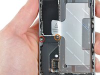
    • Use an iPod opening tool to slightly lift the top edge of the Wi-Fi antenna away from the logic board.

    • Use the tip of a spudger to pull the Wi-Fi retaining clips away from the inner frame.

    • Remove the Wi-Fi antenna from the iPhone. Make sure you don't lose the metal clips on the top of the cover where the 4.8mm screw attaches or the 4.8mm screw. That's the primary reason for abnormal Wi-Fi performance after the reassembly.

    • Before reassembly, be sure to clean all metal-to-metal contact points on the connector cover with a de-greaser such as Windex. The oils on your fingers have the potential to cause wireless interference issues. Do not clean the connectors themselves with Windex.

  15. iPhone 4 Power & Sensor Cable Replacement: step 15, image 1 of 2 iPhone 4 Power & Sensor Cable Replacement: step 15, image 2 of 2
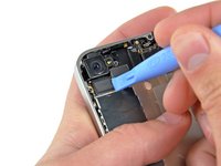
    • Use an iPod opening tool to carefully lift the rear camera connector up off its socket on the logic board.

    • Remove the rear camera.

  16. iPhone 4 Power & Sensor Cable Replacement: step 16, image 1 of 2 iPhone 4 Power & Sensor Cable Replacement: step 16, image 2 of 2
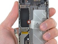
    • Remove the small circular white sticker (warranty sticker and water indicator) covering the screw near the battery pull tab.

    • Remove the 2.4 mm Phillips screw that was hidden underneath the sticker.

  17. iPhone 4 Power & Sensor Cable Replacement: step 17, image 1 of 1
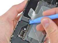
    • Use the edge of a plastic opening tool to gently pry the following connectors up and out of their sockets on the logic board:

    • Digitizer cable (pry from bottom)

    • LCD cable (pry from bottom)

    • Headphone jack/volume button cable (pry from top)

    • Top Microphone/sleep button cable (pry from top)

    • Front camera cable (pry from top)

  18. iPhone 4 Power & Sensor Cable Replacement: step 18, image 1 of 1
    Tool used on this step:
    Standoff Screwdriver for iPhones
    $5.49
    Buy
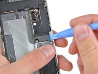
    • Remove the 4.8 mm standoff screw near the headphone jack.

    • Standoff screws are best removed using a standoff screwdriver or bit.

    • In a pinch, a small flathead screwdriver will do the job—but use extra caution to ensure it doesn't slip and damage surrounding components.

    • When reassembling the device, this standoff sets the height of the Wi-Fi shield removed in step 13. If not torqued down, the shield will be above the plane of the frame and the back will not slide into place in step 2. The shield should be flush with the headphone jack.

    • When reassembling the motherboard, ensure that its edge sits under the circled standoff, otherwise the screws will not fit.

    • When reassembling ensure that the small rubber spacer attached to the top of the motherboard is in place.

    • Without this part, the motherboard could damage the ribbon cables around it.

  19. iPhone 4 Power & Sensor Cable Replacement: step 19, image 1 of 1
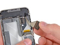
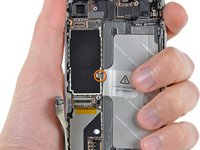
    • Carefully remove the logic board from the iPhone, minding any cables that may get caught.

    • Be careful not to damage the small gold prong (marked in red, near the top) as it's very fragile.

    • On reassembly, be careful not to trap the lower antenna cable beneath the logic board.

  20. iPhone 4 Power & Sensor Cable Replacement, Front Facing Camera: step 20, image 1 of 2 iPhone 4 Power & Sensor Cable Replacement, Front Facing Camera: step 20, image 2 of 2
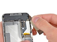
    • Use the edge of a plastic opening tool to lift the thin steel front camera retainer off the front camera.

    • Remove the front camera retainer.

    • During reassembly, position the clip's tabs on the outside of the receiving metal slots.

  21. iPhone 4 Power & Sensor Cable Replacement: step 21, image 1 of 1
    • Carefully lift the front facing camera out of the iPhone.

    • It may be helpful to use tweezers to reinstall the front camera retainer.

  22. iPhone 4 Power & Sensor Cable Replacement, Power & Sensor Cable: step 22, image 1 of 2 iPhone 4 Power & Sensor Cable Replacement, Power & Sensor Cable: step 22, image 2 of 2
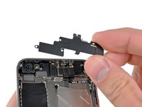
    • Remove the following two screws securing the vibrator to the inner frame:

    • One 6 mm Phillips

    • One 1.4 mm Phillips

    • Remove the vibrator from the inner case.

  23. iPhone 4 Power & Sensor Cable Replacement: step 23, image 1 of 1
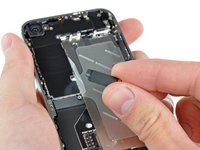
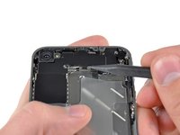
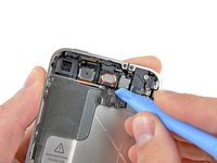
    • Use the edge of a plastic opening tool to pry the earpiece speaker away from the adhesive securing it to the front panel.

    • Be sure to pry beneath the entire speaker, and not inside it, which may cause it to split open.

  24. iPhone 4 Power & Sensor Cable Replacement: step 24, image 1 of 2 iPhone 4 Power & Sensor Cable Replacement: step 24, image 2 of 2
    • Remove the two Phillips #000 screws securing the power button bracket to the outer case.

    • Take extra care with the display cables, which can prevent easy access to the right-hand screw. The cables are easily damaged.

    • Carefully pull the power button bracket up and out of the outer case.

    • This bracket is made of cast aluminum and is very easily cracked. Proceed with caution.

  25. iPhone 4 Power & Sensor Cable Replacement: step 25, image 1 of 1
    • Use a pair of tweezers to pull the body of the headphone jack out of the outer case.

    • Take extra caution to avoid ripping the thin cable.

  26. iPhone 4 Power & Sensor Cable Replacement: step 26, image 1 of 1
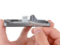
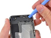
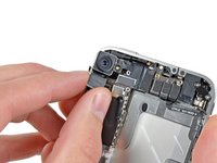
    • Grab the power & sensor cable near the microphone and peel it off the front panel, being careful not to rip it in the process.

    • Take note of the gold, rectangular microphone attached vertically to the case. Take care not to rip it when removing the cable.

  27. iPhone 4 Power & Sensor Cable Replacement: step 27, image 1 of 1
    • If you are replacing the power & sensor cable with a new unit, use the edge of a plastic opening tool to peel the electronic power switch off its metal bracket.

    • Also be sure to transfer the proximity sensor foam/UV-filter adhered to the old power & sensor cable if your new one does not already come with one. It looks like a small square and can be peeled off with tweezers.

    • Transfer the bracket to your new power & sensor cable.

Conclusion

To reassemble your device, follow these instructions in reverse order.

509 other people completed this guide.

Attached Documents

24 Comments

Be careful removing the headphone adapter, the ribbon is very easy to rib with the metal brace beneath it.

Ryan Bahr - Reply

Thank you very much for the, it has been very useful for my to change the power and sensor cable.

You are doing a very good job in this web.

rafar1980 - Reply

Now this is more helpful, than the power button repair guide that they gave us. This one still kind of leaves me hanging on how I'm supposed to put the silver button back into the hole so that it makes contact with the orange dome(aka the powerbutton).

Anthony - Reply

I replaced the Home button and the Power & Sensor cable, along with battery. Let me explain some caveats with ifixit's parts (OEM Apple parts):

-The power-sensor part does not include a new gasket/filter for the sensor- recommend tweezers and care.

-The power-sensor cable needs the foam pad transferred with the adhesive- extreme care with removal.

-IF the power button isn't working it is likely the cable, not the button.

-I used a small ice cube tray.

-It took me an hour (I had to get up and walk away...frustration factor high with the delicate flex cables and adhesive). Lit magnifier is welcome. Definitely use a spudge stick.

-I broke 2 of the 4 shield/antenna tabs that you need to tuck down from the speaker on re-assembly. I didn't force them, but so easy to press too hard in seating the speaker.

- I do repairs on a grounded-ESD mat and wore wriststrap.

-Right screw on the power button brace is PITA to access...careful pressing on the display flex cables to access the tiny screw. Magnetize your bit!

meekgeek - Reply

Great guide and perfect web site. It is extremely easy to find what you are looking for and order the components you need.

alessandronapoli - Reply

Add Comment

View Statistics:

Past 24 Hours: 2

Past 7 Days: 11

Past 30 Days: 67

All Time: 430,635