Introduction
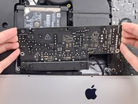
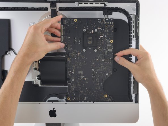
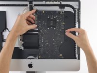
Hier wird der Ausbau des Logic Boards am 2017er iMac 4K gezeigt, damit das RAM ersetzt oder entfernt werden kann.
Einige Bilder in der Anleitung stammen von einem 2015er iMac, der geringfügige Unterschiede zeigt. Auf den Reparaturverlauf hat das keinen Einfluss.
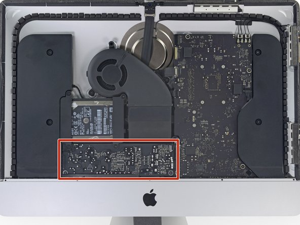
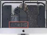
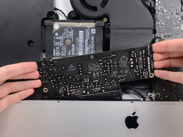
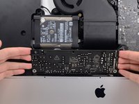
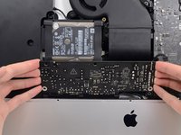
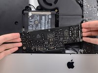
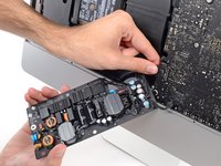
Die Anleitung ist als "potentiell gefährlich" eingestuft, weil du am Netzteil arbeiten musst, welches große Kondensatoren enthält. Ziehe den Netzstecker und halte den Einschaltknopf mindestens zehn Sekunden lang gedrückt, damit die Kondensatoren entladen werden. Fasse die Platine nur an den Kanten an und berühre keine Bauteile an der Oberfläche.
What you need
-
-
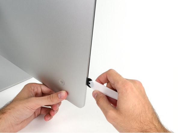
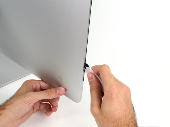
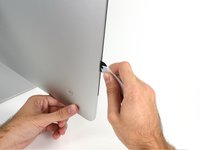
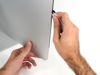
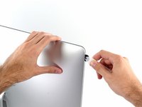
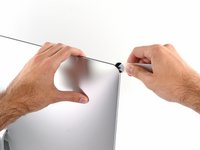
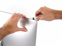
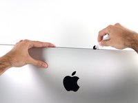
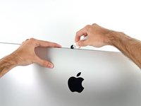
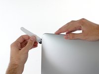
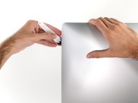
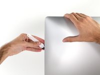
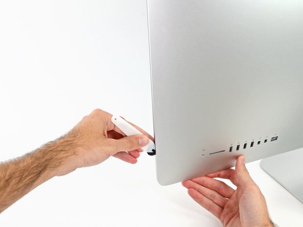
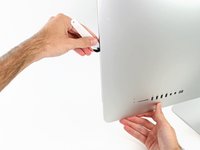
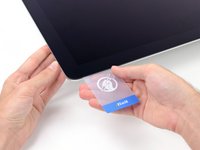
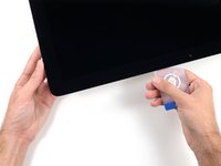
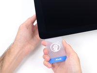
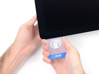
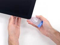
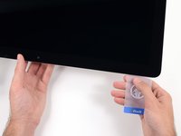
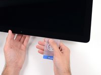
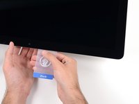
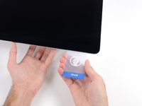
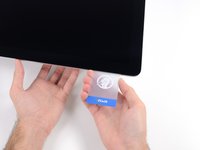
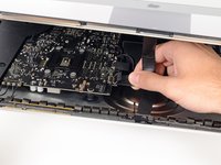
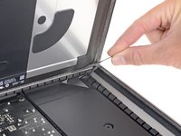
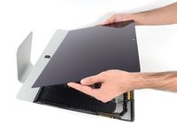
Beginne an der linken Seite des Displays, auf der Seite der Ein-/Aus-Taste, und schiebe das iMac Opening Tool zwischen Das Glaspanel und das Rückgehäuse.
-
Arbeite vorsichtig! Das Glas bricht leicht, wenn es zu stark belastet wird. Erwärme die Kanten mit einem Haartrockner und löse das Klebeband ab, wenn die Raumtemperaturen niedrig sind.
-
-
Tool used on this step:Plastic Cards$2.99
-
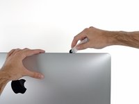
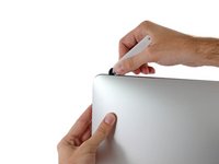
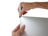
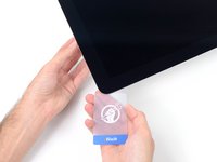
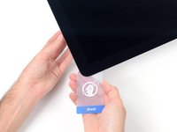
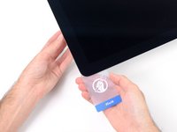
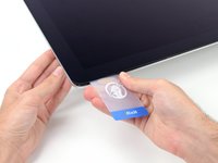
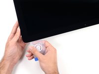
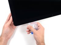
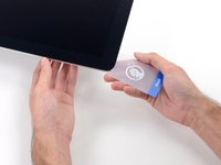
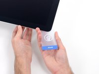
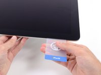
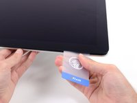
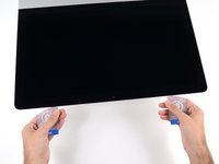
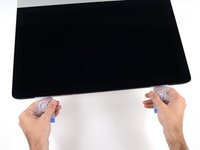
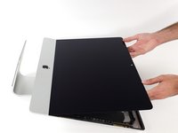
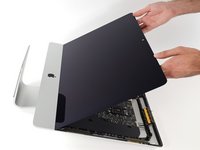
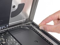
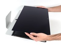
Beginne an der oberen rechten Ecke des iMacs und schiebe eine Kunststoffkarte zwischen Display und Rahmen.
-
-
-
-
Entferne folgende fünf Kreuzschlitzschrauben, welche die untere Auflagestütze befestigen:
-
Vier 3,2 mm Schrauben
-
Eine 1,7 mm Schraube
-
-
-
Entferne folgende Torx T10 Schrauben welche die Festplattenhalterungen am iMac befestigen:
-
Zwei 21 mm Schrauben
-
Eine 9 mm Schraube
-
Eine 27 mm Schraube
-
-
-
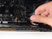
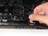
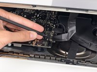
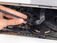
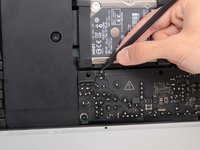
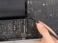
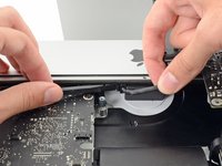
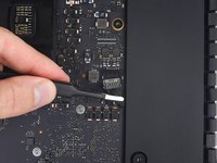
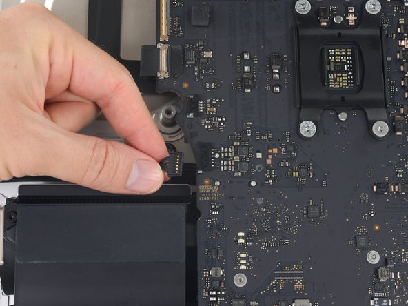
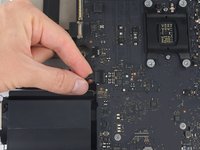
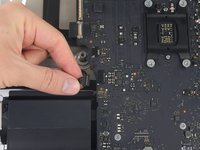
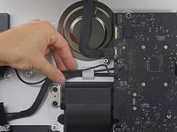
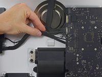
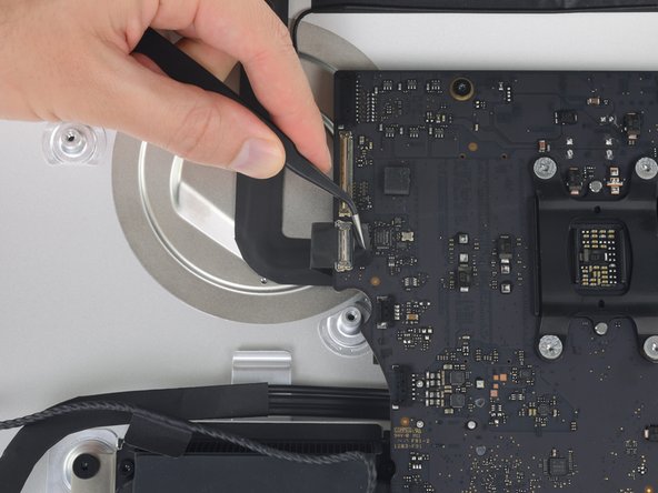
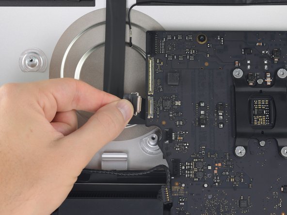
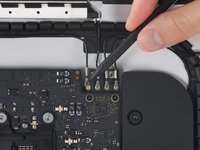
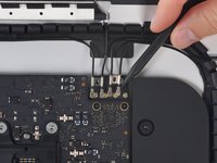
Drücke mit der Spudgerspitze abwechselnd auf jeder Seite des Steckers am Kabel zum Netzschalter und lasse ihn langsam aus dem Sockel "herauswandern".
-
-
-
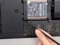
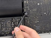
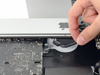
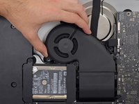
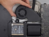
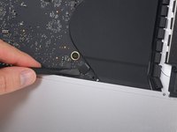
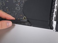
Ziehe den Lüfterstecker vorsichtig gerade aus seinem Anschluss auf dem Logic Board.
-
-
-
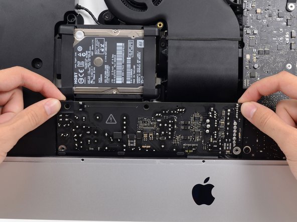
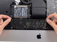
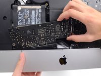
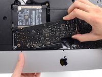
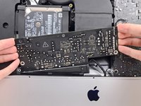
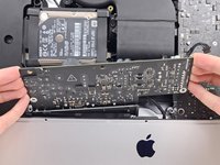
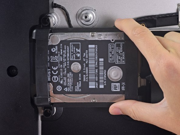
Hebe die Festplatte am Rand in der Nähe des Logic Board an und ziehe sie etwas aus ihrem Sitz.
-
-
-
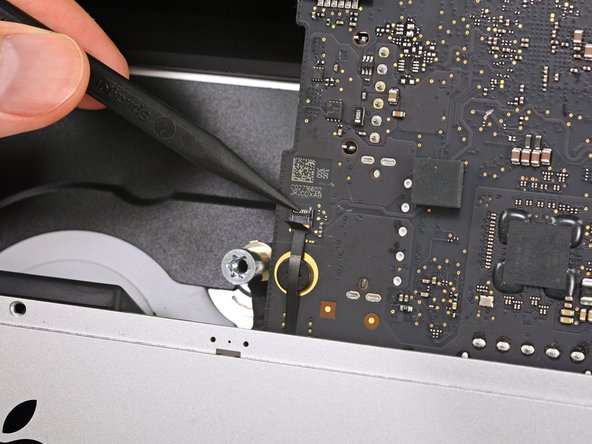
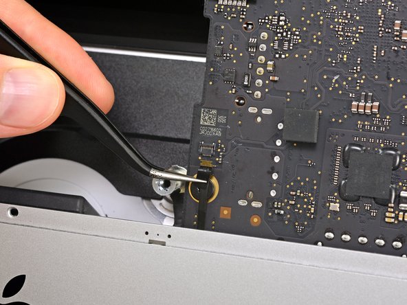
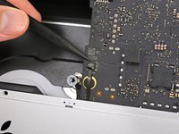
Entferne die 7,3 mm Torx T8 Schraube, welche den Festplatteneinschub am Rückgehäuse befestigt.
-
-
-
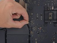
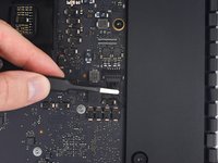
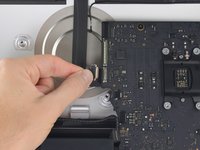
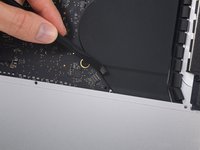
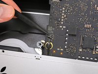
Ziehe den Stecker zum rechten Lautsprecher vorsichtig gerade herunter und aus seinem Anschluss auf dem Logic Board.
-
-
-
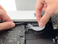
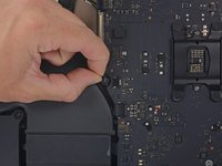
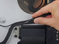
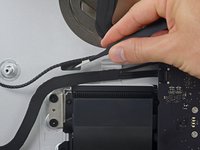
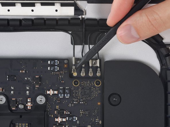
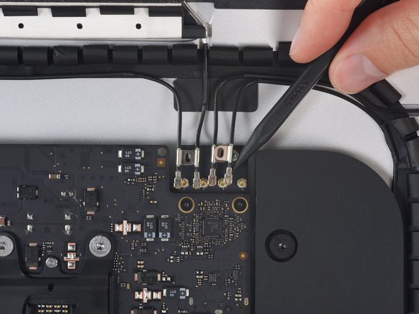
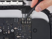
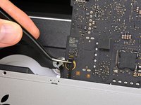
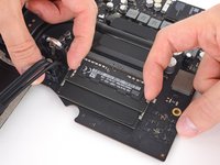
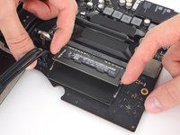
Klappe den Sicherungsbügel am ZIF Verbinder des Mikrofonkabels hoch und ziehe das Kabel aus seinem Anschluss auf dem Logic Board.
-
Das Mikrofonkabel ist empfindlich, sei also vorsichtig und beschädige es nicht in einem der nachfolgenden Schritte. Wenn es nötig ist, dann klebe es behutsam auf die Vorderseite des iMac Gehäuses, damit es nicht mehr im Weg ist und beschädigt werden kann.
-


Um dein Gerät wieder zusammenzusetzen, folge den Schritten in umgekehrter Reihenfolge.
Cancel: I did not complete this guide.
158 other people completed this guide.
Special thanks to these translators:
100%

These translators are helping us fix the world! Want to contribute?
Start translating ›

80 Guide Comments
An excellent guide - many thanks. The logic board was tricksy to get out - the card reader was jamming on the casing, but it came out with care. It's easy to trap the microphone cable and the power button cables when re-assembling, so they're worth looking out for. Successfully replaced the RAM and installed an SSD at the same time - many thanks.
Can a SSD or fusion drive be put in the place where the normal hard drive was?
An ssd can yes - that's what I did at the same time as upgrading the ram. As long as it's a 2.5" ssd it should be fine. The Samsung ssd I used was a but thinner than the hard drive that came out but that doesn't affect anything really. You'll need to either have a bootable clone of your drive, or install Sierra from a USB stick you've already prepared (which is what I did).
A Fusion drive is the terminology used by Apple when the use a board soldered 120ish Gb storage and a standard 1Tb 2.5 inch drive, and bind them together, if you throw in a 1Tb SSD in place of the existing standard hard drive you end up with 2 drives when you begin installation, you can find the instructions to merge the onboard and the new SSD back together again, and boy does it transform these machines, absolute pig with a factory fusion setup.
I also upgraded my hard-drive to a 512 GB Samsung SSD successfully along with installing the 32 GB of RAM. The guide was great, but I have a two comments.
1) The screws that hold the antenna connectors (Step 52) are were very tightly screwed into the board, and it is easy to strip the head of the screw. I stripped one of the screws… Luckily, it was easy to just pull up on the bluetooth/AirPort card and slide it out from its slot on the main board. Thus, an option to removing all the antenna wires, is to just pull the bluetooth/Airport card out. It was quite easy to slip back into the correct spot when reassembling as well.
2) It was only after I completed the repair that I realized that the top of the nice screwdriver provided in the repair kit contained more hidden bits!