Introduction
Use this guide to replace the 2230 M.2 SSD on an Xbox Series X.
Before you begin, completely power down and unplug all cables from your console. Remember to follow general electrostatic discharge (ESD) safety procedures while repairing the console.
These steps only describe how to physically remove and replace your console’s SSD. Because Microsoft formats their console drives, you may need additional software tools and procedures to get the replacement SSD to function as intended.
What you need
-
-
Use a pair of tweezers to remove the sticker hiding the first screw on the back panel, near the base.
-
-
-
Use a pair of blunt tweezers to peel back the large sticker on the back panel to reveal the second screw.
-
-
-
Use a T8 Torx driver to remove the two 7.4 mm-long screws securing the back panel.
-
-
-
Insert the flat end of a spudger into the gap between the back panel and the shell, near the left side of the base.
-
Pry up the back panel to release it from the locking clips.
-
-
-
Insert the flat end of a spudger into the gap between the back panel and the shell, near the right side of the base.
-
Pry up the back panel to release it from the locking clips.
-
-
-
Grip the back panel at the opening you just created and pull it up and away from the shell to unclip the long edges.
-
-
-
Tilt the back panel up and pull it away from the top edge of the shell to release it from the gap.
-
Remove the back panel.
-
-
-
Use a T8 Torx driver to remove the three screws securing the fan to the center chassis:
-
One 10.5 mm pancake screw
-
Two 8.8 mm screws
-
-
-
Use your fingers or a pair of blunt tweezers to grip the edges of the fan cable connector, and pull up to disconnect it from the center chassis.
-
-
-
Use the flat end of a spudger to lift up on the locking tab holding the base to the shell.
-
-
-
Grip the base and rotate it counterclockwise to unlock it from the shell.
-
Remove the base.
-
-
-
Use a T8 Torx driver to remove the two 8.8 mm screws securing the optical drive's vibration isolator to the shell: one on the base and one on the top of the isolator.
-
-
-
Use a pair of blunt tweezers to grip the edges of the optical drive power connector and pull up to disconnect it from the optical drive.
-
Use your fingers to pull up and disconnect the data cable from the optical drive.
-
-
-
Grip the top edge of the optical drive and pull it out of its slot in the shell to remove it.
-
-
-
-
Use the flat end of a spudger to flip open the metal locking tab on the USB port ribbon cable.
-
-
-
Use the pointed end of a spudger to depress the metal tab on the side of the power button cable's board connector.
-
With the metal tab depressed, use a pair of tweezers to pull up on the pull tab to disconnect the power button cable from the center chassis.
-
-
-
Use a T8 Torx driver to remove the three 7.4 mm screws securing the center chassis assembly to the shell.
-
-
-
Grip the center chassis and pull it towards the green fan grille at the top of the shell, uncoupling the guide pegs from the shell.
-
Lift out the center chassis assembly to remove it from the shell.
-
-
-
Unlatch the chassis strap from the right side of the power supply.
-
-
-
Pull the chassis strap over and off of the power supply.
-
Once the strap is off of the power supply, set the loose section to the side.
-
-
-
Use a T8 Torx driver to remove the three screws securing the power cable port to the chassis:
-
Two 13.1 mm screws
-
One 35 mm screw
-
-
-
Use a T8 Torx driver to remove the 8.8 mm screw securing the power supply corner cover.
-
-
-
Use a T8 Torx driver to remove the three 9.6 mm screws securing the accessory antenna board to the center chassis.
-
-
-
Use a T8 Torx driver to remove the nine screws securing the board shield:
-
Six 8.8 mm black screws
-
Two 35 mm silver screws
-
One 13.1 mm silver screw
-
-
-
Disconnect the chassis strap from the locking tabs on either side of the power supply.
-
-
-
Grip and compress the locking tab on the 10-pin power connector.
-
While compressing the locking tab, lift the connector straight up to disconnect it from the board.
-
-
-
Grip and compress the locking tab on the 2-pin power connector.
-
While compressing the locking tab, lift the connector straight up to disconnect it from the board.
-
-
-
Use a T8 Torx driver to remove the four screws securing the power supply around its perimeter:
-
Three 35 mm silver screws
-
One 8.8 mm black screw
-
-
-
Use a T8 Torx driver to remove the three 8.8 mm screws securing the Wi-Fi antenna board.
-
-
-
Grip the antenna board and pull it directly away from the center chassis to disconnect it.
-
Remove the antenna board.
-
-
-
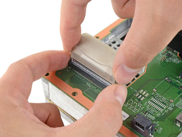
Grip the base of the interconnect cable connector with your fingers.
-
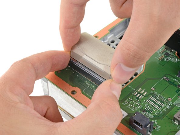
Depress each side of the connector to unlock the cable locking tabs.
-
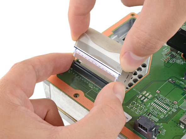
With the locking tabs depressed, grip the edges of the interconnect cable and pull it straight out of the connector to disconnect it.
-
-
-
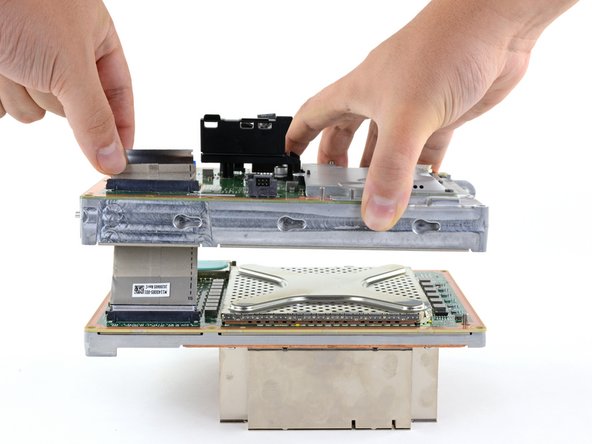
Lift the center chassis off of the motherboard and heatsink assembly.
-
Route the interconnect cable through the cutout on the center chassis as you remove it.
-
-
-
Use the flat end of a spudger to pry up the edges of the metal SSD shield.
-
Remove the SSD shield.
-
-
-
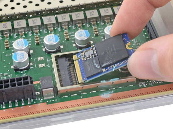
Grip the end of the SSD and pull it away from its M.2 board connector to remove it.
-