Introduction
Rebuild a dead Rollei battery with modern LiFePO4 cells.
Note that the voltage of a fully charged LiFePO4 drops slightly when power is used by the camera. This causes the camera to display an almost depleted battery (at least my 6008AF does that). This is nothing to worry about, especially since LIFePO4 batteries keep their voltage level pretty well during discharge.
What you need
Video Overview
-
-
Save the tiny screws. They are easily lost and hard to replace.
-
Watch out the cables inside may very short.
-
-
-
Depending on battery type this may look a bit different.
-
Sometimes the batteries have a very tight fit and are not to easy to remove. Try pulling with pliers
-
-
-
The original NiCd batteries had two additional cables for a temperature sensor. See yellow one, which also has the original plastic housing.
-
Be sure to dispose the old battery pack properly. They contain harmful chemicals and need special treatment for waste disposal!
-
-
-
This step helps later to have the solder stick to the batteries
-
-
-
I had to turn around one of the batteries later in the guide to allow easier soldering... depends on the wiring though.
-
-
-
Check the size of the battery pack together with the BMS Board. It should easily fit with a bit of space inside the housing. Otherwise you may get problems down the road of this guide.
-
-
-
You can also use normal thin wire, but be aware that the space within the housing is limited.
-
-
-
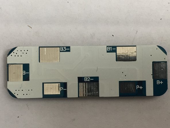
This is based on the specific PCB used and my be different for others
-
-
-
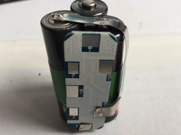
Add a bit of solder on the connector you want to use next. I started with B+ and connected it to the + pole of the first battery.
-
Test again if everything fits in the housing.
-
Warning! The housing is metal. Make sure not to short-cut something!
-
-
-
-
Again do not short cut anything!
-
The hilium connector helps here to save lots of space compared to wires
-
-
-
See the finalised soldering of Step 12
-
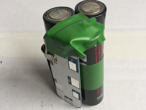
Use electric tape to isolate the finished work (this prevents shortcuts)
-
-
-
Try to isolate but do not cover the writings on the PCB so you can still see, what is already wired.
-
-
-
It is hard to get the orientation if all batteries correct on first try. But the tape allows cutting and reorientation if needed.
-
This is only needed to use less of the connector and allow easier wiring without crossings
-
-
-
Again add a bit of solder to the poles.
-
And use fold the connector tape.
-
Watch out for shortcuts
-
-
-
Now you see why the electrical tape is needed for isolation. If the connector roll is touching the wrong parts you may get a short cut, that may brick your PCB.
-
-
-
The pliers help to not burn your fingers.
-
See on 2nd picture how much space we save with the hilium connectors.
-
On 3rd picture we see how solder punctured the electrical tape. In the next step we add another layer for security.
-
-
-
Adding another layer of isolation as we have crossing hilium connectors here.
-
-
-
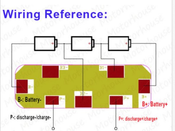
Note from the wiring diagram the B3-connector of the PCB is unused.
-
So we add electrical tape to isolate it.
-
-
-
These are the charge/discharge ports of our battery pack
-
Be sure that the length of the wire is long enough to wire it to the Rollei outlet later.
-
If you use a multimeter to check the voltage you will see it's 0V
-
The PCB needs to be activated, we do this by doing some short charging
-
-
-
A bit of charging is sufficient. The MaHa charger shows the voltage of 10,4V
-
Now also the multimeter shows the correct voltage.
-
The PCB is now activated and the battery pack correctly wired.
-
If this step is not working as expected, then check all wiring, soldering and diagrams again to validate there are no mistakes.
-
-
-
This is the most tricky soldering part.
-
Make sure there is not anything connected that shouldn't.
-
The battery has two + and two - poles. Make sure the + (white cable) is connected to the right input. Have a look at the red cables. One is going directly to the camera connector. The other one is protected by a fuse that protects your camera.
-
-
-
Find out how much foam you need by putting the battery pack with foam layers outside of the housing.
-
Keep space for wires and fuse at the top.
-
-
-
Align battery pack, lid and housing
-
Notice that the screws are on one side only.
-
Two tiny squares snap into the other side.
-
Check that the lid is closing completely, without much pressure (Pic. 3). Otherwise remove a bit foam
-
-
-
Note: the lid is now turned around (thus mirrored to the wiring diagram)
-
It is expected that the two connectors to the right produce 0V
-
Make sure you get roughly 10V with the right polarity
-
Repeat this step, to double-check. BEFORE inserting the battery into your camera.
-
-
-
Fill the two unused connectors (from the temp sensor) with hard glue. This prevents users from accidentally using a Rollei Charger N or G, which are not suitable for the battery type and might cause fire or explosion.
-
Charge the battery with a Lithium capable LiFePO4 charger only!
-
Notice that the battery has now only 81g compared to 210g for the old NiCd.
-
Happy using your Rollei again!
-
-
-
Attached you can find a STL file (under Media) to 3D-PRINT a charging tray for the new pin layout (remember blocking some pins so the Rollei Charger N cannot fry your new battery). The 3D Model can also be downloaded from here: https://www.thingiverse.com/thing:215677...
-
Print the 3D Model (or get it printed online).
-
Get a connector socket (for the charger I used I got one of these: https://bit.ly/2NwmhUo ) with 12.6mm diameter (you can use others but the 3D model might not fit then).
-
Solder wires to two pins (check the diameter of the pins so they fit the battery!) Make sure they're tick enough to have electrical contact. I used two small nails I shortened. Glue the pins into the two holes so they stick out roughly 5-6mm. Validate that the battery fits and connects (use a meter!)
-
Solder the other ends of the cables to the socket and glue the socket into the hole. Fill the bottom side of the tray with hot glue to fix everything.
-
A charger can be ordered from eBay: search for 11V Charger 1A Smart to 9.6V LiFe LiFePO4
-


Have fun with your Rollei again! :)
Have fun with your Rollei again! :)
Cancel: I did not complete this guide.
3 other people completed this guide.
43 Comments
Hello Markus,
I have followed your instructions to rebuilt the battery pack. Batteries charged as expected to 10.4V, however both of my cameras 6008I and 6008 AF showing “Charge” briefly and will not turn on with the new LiFePo4 pack. I think the selected voltage of 9.6V is probably just too low.
Thanks,
Victor Dombrovskiy
Hello Victor,
It looks like we have the same issue with our 6008 AF. Mine does not work correctly. It turns on, it meters exposure but neither AF no rewind mechanism work. I am arrfaid the reason is not voltage only, there should be other reason.
Kind regards,
Hermann
Hi,++Markus++ ,
What charger is used to charge the battery?
I am using one of these: P2012-l3 12.6v 1.5a LiPo Lithium Ion Charger for 11.1V Li-ion Battery
The PCB BMS Protection Board for 3 Packs 18650 LiFePO4 LiFe Battery Cell 3S does the balancing and cut off. So every “C.V. Voltage for LiFePo4: 10.8V±1%” should work.
Hi,Markus,
That link had been failed.I want to ask is you list charge is a DC mount, how to contact with battery ? battery has six holes.If you provide a photo when charging battery is very good.
The battery has 6 holes. 2 are unused (temperature sensor needed only for original charger). Thats the ones closed so the converted battery cannot end up in a Rollei Charger that might fry/burn them. The other 4 pins are both battery out. Fused and unfused. The fused are needed to not break the motor of the camera if the film is stuck in the magazine. So for charging both pairs are be fine (as long as the charging current is lower than the 1A of the fuse). I used the two center pins (unfused) in the 3D printed case.
Markus -
This is my charging tray: https://www.thingiverse.com/thing:215677...
and again a link for the exact charger I use: https://www.ebay.com/itm/P2012-l3-12-6v-...
The 3.7V batteries would be LiIon not LiFePO4. the LiFePO4 have 3.33V which adds up to the 10V. 3.7V * 3 sums up to 11.1V. Which I didn’t want to try back then (risk of damaging the camera with over voltage). But there is now a company offering LiPo battery replacements (see here for picture: https://www.photoscala.de/2017/10/05/neu...).
SO to sum it up, the 11.1V doesn’t seem to be a problem for the cameras. To do so, you will need another BMS Board (for 3S LiPO/LiIon) though to have another cutoff voltage.
I’ve had a lot of trouble with batteries, and had multiple versions of rebuilds. The LiPo rebuilds won’t work with the 6008AF. I don’t think this will reliably work either. PLUS. You’re bypassing the temp sensor. That means you risk frying your main board on the camera. Impossible to buy. The batteries that have been converted previously to LiPo have the sensor removed, meaning they can’t be rebuilt properly. So the supply of good shells is dwindling. I have two fully empty shells that were sold to me as fully functioning. Not.
Essentially, the guys who really know these cameras are suggesting NiMH Only, especially for the 6008AF.
The temperature sensor isn’t even used by the camera. Take a look into the slot of the camera with the battery removed. There are just 4 pins. The original Rollei charger has 6 pins and uses the temperature sensor. There are aftermarket chargers (e.g. MaHa) that have a magnetic temperature sensor to not fry the battery. The problems you might have seen is the high current draw peak of the linear aperture motors (up to 4.5A)!
Markus -
Well I also had lots of troubles with batteries. The NiMH variants (self build and ready made pick from China) both had too low voltage for my 6008AF. (I was using the MaHa charger to charge). Then I had many trails with LiIon and Voltage converters (1 and 3 cells). The LiFe setup as described above works for me. The camera is fully functional on a battery that has been charged 6 months ago (don’t have PQS lenses though). Your comment on the thermal sensor and motherboard frying is completely wrong. The sensor is to prevent overheating while charging. What you’re referring to is the fuse. Just look inside the battery compartment of the camera the thermal sensor isn’t even connected.
Please I’m making the battery with the Soshine 3.2V 700mAh AA /14500 LiFePO4. But I have Charger N for my Roolei old batteries and where i can found now a charger for the new batteries. Because i don’t want to reopen everytime to charge. In the pictures i see a charger but i don’ tfind in Ebay. Please write me one. Thanks
Hi Carlos,
You basically need an CCCV charger for LiFe. If you got the BMC built in it it will handle the balancing of the three cells and cut off if charged.
Basically the search term is LiFePo4 charger 3S (3 cells) e.g. something like that: https://m.aliexpress.com/item/3281134765...
I also created a 3D Model for a charger stand (to be 3D printed) . If you like I have a spare set (unused that I would sell) . Otherwise the model is available here: https://www.thingiverse.com/thing:215677...
Currently this link can be used to order a charger: https://www.ebay.com/itm/11V-Charger-1A-...
What did you use for the metal pins in your charger base? I’m having some trouble finding suitable ones to make a connector for the battery charger.
The pins (to solder on somewhere) that are readily available all are either to thin (1mm) or too thick. So I ended up using two small nails I had available with 1,5mm diameter. Just make sure to shorted with pliers. Also used some sanding paper to get rid of the rust proving surface to make sure there is electric conductivity. When gluing in the „pins“ I made sure they have a slight angle on a few degrees so it actually „locks“ the battery slightly .
Markus -
Thanks for the info on the pins Markus. I was able to complete the battery with 3 600mAh LiFePO4 2C cells, however my 6008 just says “Charge” when trying to use the pack. I thought that may be due to the 2C discharge rate being too low, but I tried this battery LiPO upgrade in this method: https://www.photrio.com/forum/threads/th... and still only got a “Charge” message from my camera. What I’m wondering now is if there’s just something wrong with my camera in how it is checking battery power, but that’s beyond my current electronics ability to know what to look for. I did notice that even with my NiMH packs it says “Charge” as soon as they fall from peak voltage off the charger down to their nominal output.
Hi Justin,
sorry to hear that. I just have a 6008AF which shows a half full battery with the 10V of my pack. It stays in a functional state for months without recharge and I am able to use the camera for many roles of film. I was initially trying to get this done with LiIon batteries and step-down bucket converter, but those didn’t deliver the needed current for the camera. It’s the linear motors of the shutter that has high initial drain. You can check if the current is too high by powering the camera without a lens attached. If it works then the maximum current delivered by the pack is not sufficient. Otherwise your camera wants to have a higher voltage. I was scared to fry the camera if i use much higher voltage. 3x3,7V of LiIon for example. But meanwhile I know Wiesner Phototechnik created a 11,1V pack so I guess it would have been ok. But after charging the LiIons tend to have 4,1-4,2V which would be 12,6V not sure if s.o. here know this would be too much.
Markus -
Sorry its Phototechnik Wiese: https://www.photoscala.de/2017/10/05/neu...
They also use LiPo 11,1V packs like those you (?) linked above. I was also looking into that, but didn’t find a pack that would fit into the original case.
I had the issues you have with the camera showing “Charge” with a premanufactured NiMh pack I purchased from eBay, wich just had 9,6V. The cameras seem to be very picky on the voltage.
Also the high initial drain creates a voltage drop on many batteries. I tried to measure the current once, but the tools I had supported max. 2A and those I got.
Also check what the battery management board you use can handle as max current. That could also be the bottleneck. Or the type of wiring inside the battery. Thats why I used those flat connectors.
Thanks Markus, you’re right they do seem to be extremely picky on the voltages they’ll work with. I think there may just be something wrong with my current 6008 due to what I described earlier. My brother shipped me his 6008 to try and it worked perfectly with the 9.6v and 11.1v packs. It even seems to last long using the NiMH packs I was trying in mine. I guess I may need to pack up my body and ship it out to Paepke Fototechnik for a checkup and possible repair.
Justin -
Hi! Thank you for an awesome manual! I’m just about to make this build, and I’m waiting for all the parts. I just wonder if I can use this charger that I already own, will the PCB regulate this? It’s an 12.6v 1,6A. Or do I need to buy the 11v -1A that you linked?
All the best,
Simon
Hi Simon, depends on the max Voltage specs for the BMS. Check the max. input voltage in the datasheet. I would assume it to be fine but make sure to check before so you don’t fry the BMS.
Markus -
Just checked: Charging voltageDC:11V CC/CV so you need an 11V CC/CV charger for it (at least from what I can see from the data sheet).
Markus -
Thank you so much Markus! I’ll get the 11v charger then to be safe!
Hi again Markus! Just wondering, is the BMS only regulating the charging part? If I went the route of charging the individual cells outside in a normal charger for LiFePO4 batteries with a BMS built in, would I still need the BMS? Otherwise I could just use a standard AA-cradle so you can easily take them in and out once you screw the pack open.
The BMS is doing the balancing of the pack. If you don’t have one you’ll have to charge each cell
individually to not fry one while trying to get the others to the same charge level. You’ll have to get the cells out of the Rollei battery case each time nothing I would recommend. It’s rather tight in there.
I know some guys have built replacements with LiPo packs. Look for Turnigy nano-tech 11.1V packs. EFLB4503SJ30 or https://www.amazon.com/Turnigy-Nano-tech... but the second one is supposed to be very tight. Be sure to check the size before. Also you have to get the balancer connector accessible some how. But that would be less soldering.
Markus -
Which terminals should I be charging the battery with?
Will a multi charger be OK?
I used the two center pins because the + wire by-passes the fuse then. Whats a multi charger? The BMS module just needs the correct voltage. If you have exactly the same BMS then take any 11V CC/CV charger like shown above (or any that works within specs of the BMS module).
Markus -
Thanks for your reply.
The battery pack I have has been re-packed with 8 No. 1.2v NiMh batteries.
So 9.6 volts.
Will this be enough to run the camera?
I have a charger now so I can charge the pack up & see what happens!
I have a camera & 3 lenses & just wanted to test it all before I sold it for the son in law.
Ended up costing me about £200.00 so far!
it works. shutter speeds etc etc. lenses all ok apart from 1 which has a displaced aperture blade.
But.
always shows under exposed in the display?
is this an easy fix?
For Step 30 - can you add pictures of the bottom of your charging tray where you've soldered the pins to the charging terminal? I've just 3D printed out the frame and got all the parts together, but I'm unsure how to connect the charger wiring.
Hi Cameron, dang I don’t have a picture from below before being having the glued.
but I can describe a bit mor in detail. Take two nails and test them to get the proper length and diameter. Then take the wires and loop them just above the nail head (with the tip of the nail pointing up). Then solder it there (the head of the nail will prevent it slipping off. Then test the length by putting the nails from the bottom into the holes of the battery socket. The soldered cables should be just at the underside if the holes. If everting is fine, put the cable true the jack hole (inside out). Solder it correctly to the jack. Test polarity and then glue or press the jack hole. Put the cable inside and file the hole from the bottom with hot glue or similar.
Markus -
Thank you Markus - I'll give that a shot. I successfully built the battery and charged it manually with a power station for the time being. I put it back in the body I got at a photo auction and it works (mostly)!
Shutter speeds, mirror function, and remote trigger all seem to work. However, the data readout is inverted (almost as if the camera is expecting the prism finder to flip the information left to right). Waist level finder is backwards but prism finder properly flips the readout to the appropriate order. Any ideas as to how to switch this? Might be old electronics that are fried too. Not a deal breaker for me.
Hi , I built this based on your direction but when I charge after while I still get zero volt when I disconnect from the charger
what can be the problem?
The BMS might be in blocking mode. Check the technical specs, you might need to set a voltage to a set of pins to activate it. usually this is done with a full charge, but might be dependent on the BMS specs. Other options… it might be just faulty or broken due to excessive heat while soldering. Take a look here: https://electronics.stackexchange.com/qu...
Markus -
Thanks Markus for making this, I have SLX camera and I made the battery pack based on your direction, and charged it I get 9.6V from battery, but when I put the battery the camera doesnt work and battery goes back to 0 volt
any idea what is wrong with it?
note: the camera was working with the original batteries but wanted to renew batteries so there is no problem with camera