Introduction
This guide show how to disassemble the mechanism that moves the mirror in a Pentax MX. The cause of many jammed cameras can be traced to the mirror box mechanism. If a latch is stuck or sluggish, it can prevent proper winding or the completion of an exposure cycle. Disassembly and cleaning will often restore functionality.
What you need
-
-
Remove the lever cap. The cap is reverse threaded.
-
Lift off the advance lever.
-
Remove the collar beneath the lever.
-
-
-
Set the ISO to 100 and the shutter speed to 1000.
-
Remove one pin head screw.
-
Lift off shutter speed dial.
-
Remove the collar beneath the dial.
-
Installation Notes: Make sure that the tab on the shutter speed resistor mates properly with this slot on the shutter speed dial.
-
-
-
Place a tool in the fork of the rewind shaft. Turn the rewind knob counterclockwise to loosen it.
-
Remove the lock ring underneath the rewind knob.
-
Remove the cover plate.
-
-
-
Remove two M1.7 x 3.2 mm screws.
-
Remove two M1.7 x 2 mm countersunk screws.
-
Lift off top cover.
-
The release cable pin in the shutter button is loose and may fall out.
-
-
-
Apply isopropyl alcohol to soften the leatherette adhesive.
-
Turn the self-timer lever to the charged position.
-
Peel the leatherette off the camera body, carefully working it over the self-timer lever.
-
Remove one loose cover panel.
-
Repeat for the opposite panel.
-
-
-
Remove four M1.9 x 3.9 mm screws.
-
Lift off front board.
-
Look for shim washers at the screw locations and note their positions.
-
-
-
Remove three M1.7 x 2.0 mm countersunk screws.
-
Lift off bottom cover.
-
Remove loose plastic housing for motor drive contacts.
-
-
-
Remove four M1.9 x 3.8 mm screws.
-
Lift off lens mount baffle.
-
Use isopropyl alcohol to soften adhesive and detach wires from the backside of the baffle.
-
-
-
Unsolder two brown wires for the shutter speed resistor.
-
-
-
-
Unsolder one gray for the x-sync.
-
Unsolder one white wire for the FP sync.
-
-
-
Unsolder one green wire for the motor drive connection.
-
Unsolder one blue wire for the LED switch.
-
Unsolder one red wire and one black wire.
-
-
-
Open up wire routing guides and remove all wires from them.
-
Pull the black and red wires out of the hole in the bottom of the chassis.
-
Make sure the gray wire is free and can pull away with the mirror box.
-
-
-
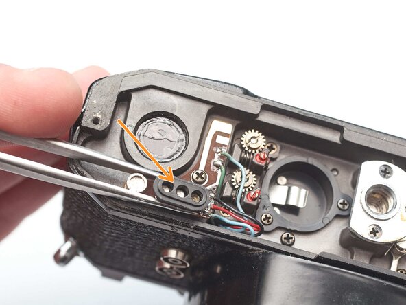
Remove one M1.4 x 2.8 mm screw and washer.
-
Remove one M1.7 x 2.8 mm screw.
-
Pull the LED PCB out of the side of the mirror box.
-
-
-
Loosen the slotted post but do not remove.
-
Slide the idler gear back so that it no longer engages with the speed indicator disc.
-
-
-
Remove two M1.7 x 4.6 mm screws.
-
Remove two slotted posts.
-
Lift the mirror box up and tilt the top forward to remove it.
-
-
-
Temporarily install the wind lever and the shutter speed dial.
-
Wind the camera.
-
Press the shutter release button.
-
Release the opening curtain latch. This is usually done by the mirror box but has to be done manually in this case.
-
-
-
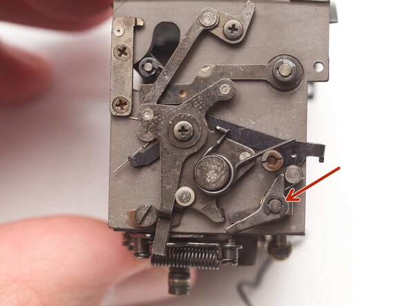
The mirror release latch should move freely and snap back to its home position.
-
Push up on the post to activate the depth of field preview function.
-
To charge the mirror, push the post on the bottom of the mirror box forward.
-
Push the mirror release latch down to flip up the mirror.
-
Push the mirror return latch rearward to flip the mirror down.
-
LED Switch (blue wire) and FP flash sync (white wire) should be open when the mirror is down and close when the mirror is up.
-
-
-
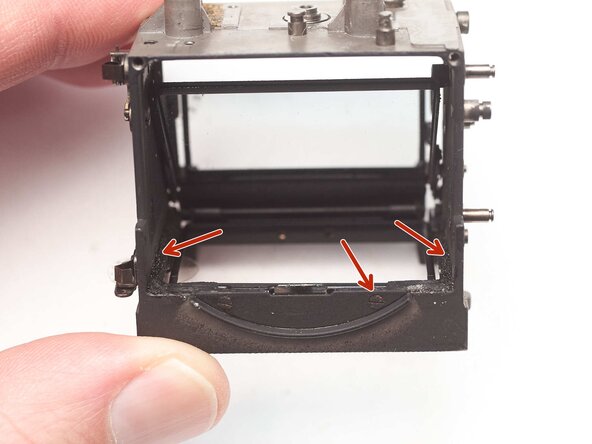
Remove two screws.
-
Look for shim washer under the mounting plate.
-
-
-
Remove one M2 circlip and shim washer.
-
Note the position of the bias spring for reassembly.
-
Remove mirror release latch.
-
Remove shim washer.
-
-
-
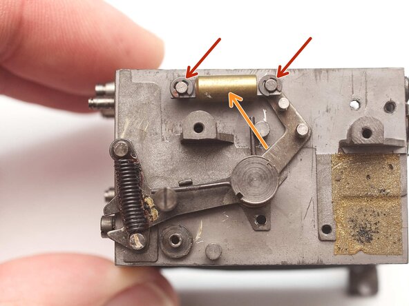
Remove two M1.4 x 3.4mm screws.
-
Remove upper mirror actuation lever.
-
Remove loose plastic bushing. This may stick to the actuation lever.
-
Installation Notes: Make sure that the actuation levers are properly coupled with the charge levers on the bottom of the mirror box.
-
-
-
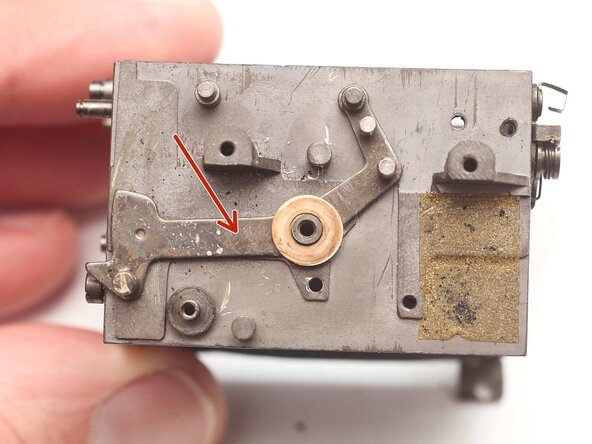
Remove the lower mirror actuation lever.
-
Remove shim washer.
-
Installation Notes: Make sure the bias spring is properly placed.
-
-
-
Remove one M2 circlip.
-
Remove shim washer.
-
Remove mirror lifting lever.
-
-
-
Remove two M1.7 x 2.4mm screws.
-
Remove LED switch contact.
-
Remove two M1.7 x 2.4mm screws.
-
Remove FP sync contact.
-
-
-
Remove one M1.4 x 3.3 mm screw.
-
Remove mirror return latch.
-
Remove bias spring and shim washer.
-
-
-
Detach and remove mirror lifting spring.
-
Detach mirror return spring.
-
Remove lever screw using a spanner wrench. The return spring may still have some tension in it.
-
Lift off mirror return lever.
-
Remove shim washers.
-
This piece of foam is used to silence the coil spring. It can be replaced or removed. If removed, a small piece of heat shrink placed around the coil spring can act as a silencer.
-
-
-
Clean all shafts on the mirror box with isopropyl alcohol. Remove any other visible grease.
-
Clean all levers and mechanism parts especially the pivots.
-
Lubrication for the mirror box mechanism is minimal. No oil is recommended.
-
A heavy molybdenum grease should be used on high friction latching points to reduce wear.
-
This is also a good time to replace the mirror bumper foam.
-


To reassemble your device, follow these instructions in reverse order.