Free Shipping on Domestic Orders $75+

Opening Procedure

Prerequisite Only
This is a prerequisite-only guide! This guide is part of another procedure and isn’t meant to be used alone.

What you need

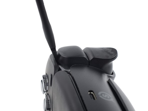
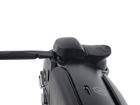
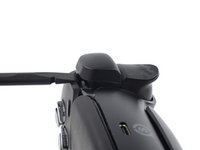
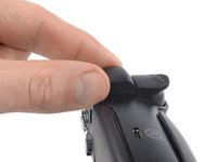
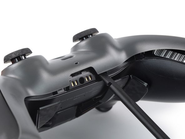
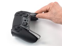
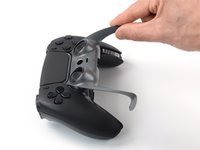
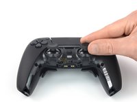
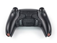
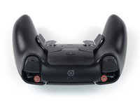
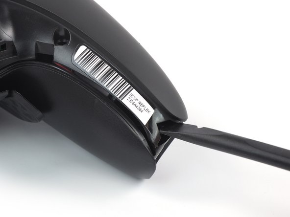
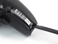
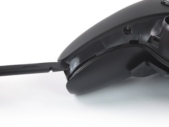
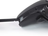
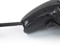
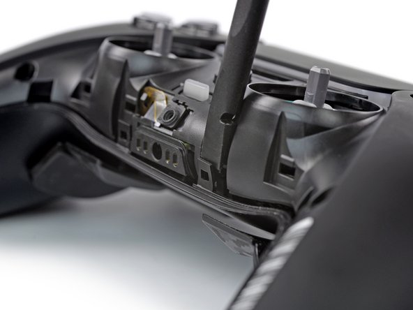
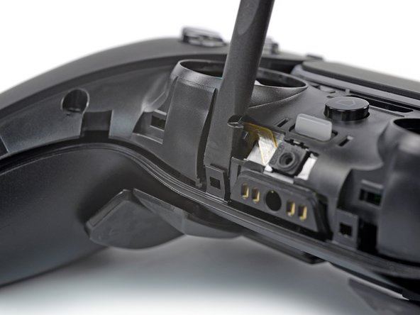
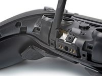
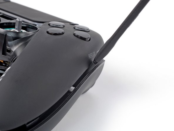
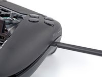
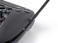
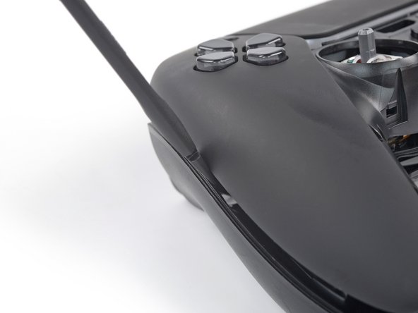
    1. Opening Procedure, Pry up the R1 bumper: step 1, image 1 of 3 Opening Procedure, Pry up the R1 bumper: step 1, image 2 of 3 Opening Procedure, Pry up the R1 bumper: step 1, image 3 of 3
      • Before starting repairs, turn off your device and unplug any cables.

      • Insert the flat end of a spudger between the faceplate and the R1 bumper.

      • Pry up with the spudger to release the clips securing the bumper.

      Ask FixBot

      Add Comment

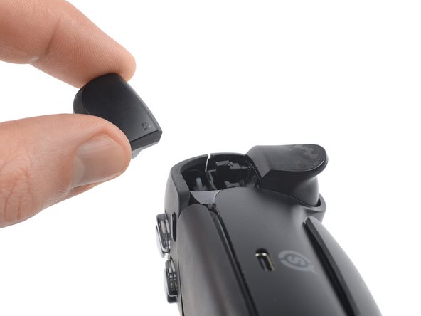
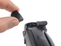
    2. Opening Procedure, Remove the R1 bumper: step 2, image 1 of 2 Opening Procedure, Remove the R1 bumper: step 2, image 2 of 2
      • Remove the R1 bumper.

      Ask FixBot

      Add Comment

    3. Opening Procedure, Pry up the L1 bumper: step 3, image 1 of 3 Opening Procedure, Pry up the L1 bumper: step 3, image 2 of 3 Opening Procedure, Pry up the L1 bumper: step 3, image 3 of 3
      • Insert the flat end of a spudger between the faceplate and the L1 bumper.

      • Pry up with the spudger to release the clips securing the bumper.

      Ask FixBot

      Add Comment

    4. Opening Procedure, Remove the L1 bumper: step 4, image 1 of 2 Opening Procedure, Remove the L1 bumper: step 4, image 2 of 2
      • Remove the L1 bumper.

      • To reinstall the bumpers, place them in their original position and firmly push them into place.

      Ask FixBot

      Add Comment

    1. Opening Procedure, Pry up the right faceplate trim edge: step 5, image 1 of 3 Opening Procedure, Pry up the right faceplate trim edge: step 5, image 2 of 3 Opening Procedure, Pry up the right faceplate trim edge: step 5, image 3 of 3
      • The faceplate trim is secured by plastic clips.

      • At the bottom tip of the right grip, insert the flat end of a spudger or a clean fingernail between the faceplate trim and the back cover.

      • Pry up to release the faceplate trim’s bottom right clip.

      Ask FixBot

      Add Comment

    2. Opening Procedure, Pry up the left faceplate trim edge: step 6, image 1 of 3 Opening Procedure, Pry up the left faceplate trim edge: step 6, image 2 of 3 Opening Procedure, Pry up the left faceplate trim edge: step 6, image 3 of 3
      • At the bottom tip of the left grip, insert the flat end of a spudger or a clean fingernail between the faceplate trim and the back cover.

      • Pry up to release the faceplate trim’s bottom left clip.

      Ask FixBot

      Add Comment

    3. Opening Procedure, Pry up the center of the faceplate trim: step 7, image 1 of 2 Opening Procedure, Pry up the center of the faceplate trim: step 7, image 2 of 2
      • Insert the flat end of a spudger between the faceplate trim and the back cover, next to the headphone jack.

      • Pry up to release the plastic clips securing the center of the faceplate trim.

      Ask FixBot

      Add Comment

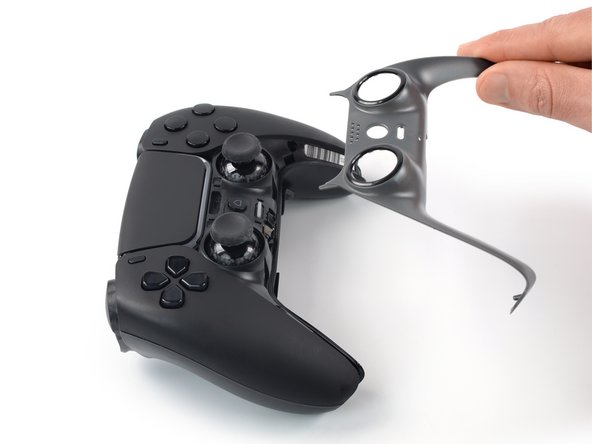
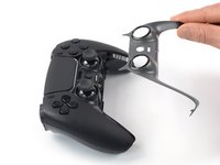
    4. Opening Procedure, Remove the faceplate trim: step 8, image 1 of 3 Opening Procedure, Remove the faceplate trim: step 8, image 2 of 3 Opening Procedure, Remove the faceplate trim: step 8, image 3 of 3
      • The top corners of the faceplate trim are slotted up underneath the faceplate.

      • Lift the bottom edge of the faceplate trim and thread it up and over the thumbsticks.

      • Pull the top corners of the faceplate trim out from underneath the faceplate and remove the faceplate trim.

      • To reinstall the faceplate trim, slide its top corners under the faceplate and over the thumbsticks, then push down along the edges of the trim to engage the clips securing it.

      Ask FixBot

      Add Comment

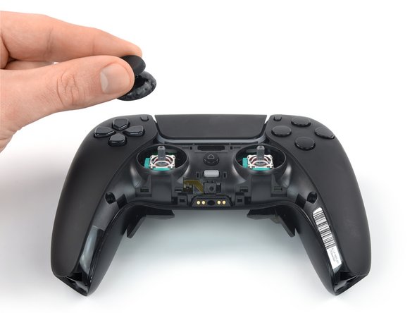
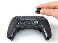
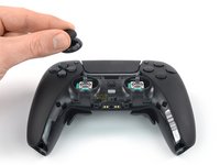
    1. Opening Procedure, Remove the thumbsticks: step 9, image 1 of 3 Opening Procedure, Remove the thumbsticks: step 9, image 2 of 3 Opening Procedure, Remove the thumbsticks: step 9, image 3 of 3
      • Pull the thumbsticks straight up and off of their joysticks to remove them.

      • To reinstall the thumbsticks, place them in their original position and push down until they lock in place.

      Ask FixBot

      Add Comment

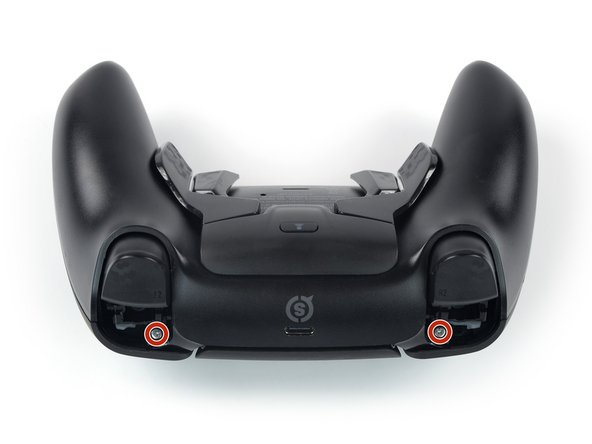
    1. Opening Procedure, Unfasten the back cover: step 10, image 1 of 2 Opening Procedure, Unfasten the back cover: step 10, image 2 of 2
      • Use a Phillips screwdriver to remove the four 6.5 mm-long screws securing the back cover, two near the triggers and two at the bottoms of the grips.

      Ask FixBot

      Add Comment

    2. Opening Procedure, Pry up the faceplate: step 11, image 1 of 2 Opening Procedure, Pry up the faceplate: step 11, image 2 of 2
      • The faceplate is secured by plastic clips.

      • Insert a spudger underneath the bottom right corner of the faceplate and pry up to release the plastic clip.

      Ask FixBot

      Add Comment

    3. Opening Procedure: step 12, image 1 of 2 Opening Procedure: step 12, image 2 of 2
      • Insert a spudger underneath the bottom left corner of the faceplate and pry up to release the plastic clip.

      Ask FixBot

      Add Comment

    4. Opening Procedure: step 13, image 1 of 3 Opening Procedure: step 13, image 2 of 3 Opening Procedure: step 13, image 3 of 3
      • Insert the flat end of a spudger between the plastic clip next to the headphone jack and the faceplate.

      • Pry the plastic clip away from the faceplate to release it.

      • Repeat to release the second clip.

      Ask FixBot

      Add Comment

    5. Opening Procedure: step 14, image 1 of 2 Opening Procedure: step 14, image 2 of 2
      • Insert the flat end of a spudger between the right edge of the faceplate and the back cover.

      • Pry down to release the plastic clip securing the faceplate.

      Ask FixBot

      Add Comment

    6. Opening Procedure: step 15, image 1 of 2 Opening Procedure: step 15, image 2 of 2
      • Insert the flat end of a spudger between the left edge of the faceplate and the back cover.

      • Pry down to release the plastic clip securing the faceplate.

      Ask FixBot

      Add Comment

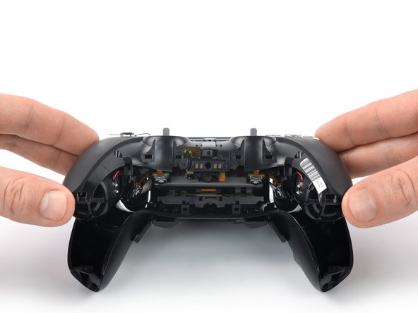
    7. Opening Procedure, Remove the front cover assembly: step 16, image 1 of 3 Opening Procedure, Remove the front cover assembly: step 16, image 2 of 3 Opening Procedure, Remove the front cover assembly: step 16, image 3 of 3
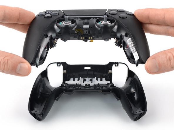
      • Carefully lift up the bottom of the faceplate assembly.

      • Pull the faceplate assembly down and remove it.

      • During reassembly, guide the triggers and the profile button through their cutouts in the back cover. Then press the faceplate assembly firmly into the back cover to engage the plastic clips securing it.

      Ask FixBot

      Add Comment

Conclusion

To reassemble your device, follow these instructions in reverse order.

Cancel: I did not complete this guide.

Dominik Schnabelrauch

Member since: 11/23/16

265,703 Reputation

682 Guides authored

Team

iFixit Member of iFixit

Staff

122 Members

72,401 Guides authored

0 Guide Comments

Add Comment

View Statistics:

Past 24 Hours: 1

Past 7 Days: 5

Past 30 Days: 13

All Time: 207