
Motherboard Removal

Prerequisite Only
This guide is only intended to be used as a prerequisite for other guides. It's incomplete by itself.

What you need

  1. Motherboard Removal, Eject the SIM card tray: step 1, image 1 of 3 Motherboard Removal, Eject the SIM card tray: step 1, image 2 of 3 Motherboard Removal, Eject the SIM card tray: step 1, image 3 of 3
    • Insert a SIM eject tool, bit, or straightened paper clip into the SIM tray hole.

    • Press directly into the hole to eject the SIM card tray.

    • Remove the SIM card tray.

  2. Motherboard Removal, Precautionary Notes: step 2, image 1 of 3 Motherboard Removal, Precautionary Notes: step 2, image 2 of 3 Motherboard Removal, Precautionary Notes: step 2, image 3 of 3
    • You will need to pry the screen up to remove it from the phone. Read the following notes carefully before proceeding.

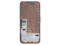
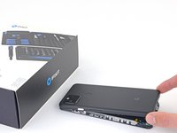
    • Take note of the two seams on the edge of your phone:

    • Screen seam: This seam separates the screen from the rest of the phone. This is where you have to pry.

    • Frame seam: This is where the plastic frame meets the back cover. It is held in place by screws. Do not pry at this seam.

    • Before you begin, note the following areas on the screen:

    • Screen flex cable: Do not insert the opening pick deeper than instructed or you risk damaging this cable.

    • Adhesive perimeter: Prying beyond this narrow perimeter without angling the pick will damage the OLED panel.

  3. Motherboard Removal, Heat the right edge of the screen: step 3, image 1 of 1
    • Apply a heated iOpener to the right edge of the display for one minute to soften the adhesive.

    • A hair dryer, heat gun, or hot plate may also be used, but be careful not to overheat the phone—the display and internal battery are both susceptible to heat damage.

  4. Motherboard Removal, Insert an opening pick: step 4, image 1 of 3 Motherboard Removal, Insert an opening pick: step 4, image 2 of 3 Motherboard Removal, Insert an opening pick: step 4, image 3 of 3
    • If your display is badly cracked, covering it with a layer of clear packing tape may allow the suction cup to adhere. Alternatively, very strong tape may be used instead of the suction cup. If all else fails, you can superglue the suction cup to the broken screen.

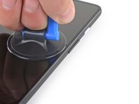
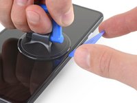
    • Place a suction cup as close to the right edge of the screen as possible.

    • Lift the suction cup with a strong steady force.

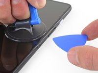
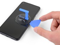
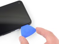
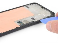
    • Insert the tip of an opening pick into the screen seam no more than 1 mm.

  5. Motherboard Removal, Guide the opening pick under the OLED panel: step 5, image 1 of 3 Motherboard Removal, Guide the opening pick under the OLED panel: step 5, image 2 of 3 Motherboard Removal, Guide the opening pick under the OLED panel: step 5, image 3 of 3
    • This step shows how to insert your pick without damaging the OLED panel. Do this before slicing the adhesive.

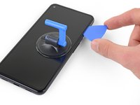
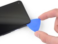
    • With the pick 1 mm into the gap, pivot the pick upwards to a steep angle.

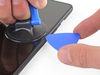
    • At a steep angle, carefully push the pick into the gap about 1/4 inch (6 mm). The pick should slide in below the OLED panel.

    • Stop if you feel the point of the pick hitting a ridge. The pick may be pressing against the edge of the OLED panel. Angle the pick and try again.

  6. Motherboard Removal, Slice through the display adhesive: step 6, image 1 of 3 Motherboard Removal, Slice through the display adhesive: step 6, image 2 of 3 Motherboard Removal, Slice through the display adhesive: step 6, image 3 of 3
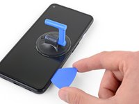
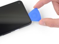
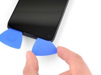
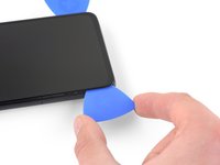
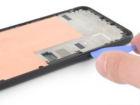
    • Slide the pick along the right edge of the screen to cut the adhesive.

    • Do not insert the pick more than 1/4 inch (6 mm) or you may damage the screen's flex cable.

    • Leave the pick in the bottom-right corner to prevent the adhesive from re-sealing.

  7. Motherboard Removal: step 7, image 1 of 3 Motherboard Removal: step 7, image 2 of 3 Motherboard Removal: step 7, image 3 of 3
    • There's a mesh covering the earpiece speaker on the top edge of the screen. If you don’t have a replacement mesh, take care not to damage or lose this component.

    • The screen adhesive is weak, so you should not need to re-apply heat. If the screen is hard to slice, apply heat to the difficult area for one minute and try again.

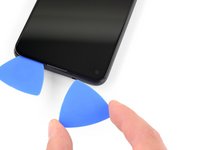
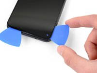
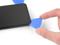
    • Insert another opening pick into the right edge of the phone at an angle where a gap has already formed to prevent damage to the OLED panel.

    • Slide the opening pick around the top of the phone to cut the adhesive.

    • Leave the pick inserted along the top edge to prevent the adhesive from resealing.

  8. Motherboard Removal: step 8, image 1 of 3 Motherboard Removal: step 8, image 2 of 3 Motherboard Removal: step 8, image 3 of 3
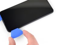
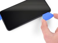
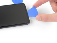
    • Insert another opening pick into the top edge of your phone at an angle where a gap has already formed to prevent damage to the OLED panel.

    • Use the pick to slice around the top-left corner where the camera window is.

    • If the screen is hard to slice, apply heat to the difficult area for one minute and try again.

    • Leave the pick inserted along the left edge of your phone to prevent the adhesive from re-sealing.

  9. Motherboard Removal: step 9, image 1 of 3 Motherboard Removal: step 9, image 2 of 3 Motherboard Removal: step 9, image 3 of 3
    • Slide the opening pick to cut the adhesive along the left edge of your phone.

    • If the screen is hard to slice, apply heat to the difficult area for one minute and try again.

    • Keep in mind that you are now slicing near the screen flex cable and digitizer.

  10. Motherboard Removal: step 10, image 1 of 3 Motherboard Removal: step 10, image 2 of 3 Motherboard Removal: step 10, image 3 of 3
    • Slide the opening pick around the bottom-left corner and across the bottom of the display to cut the rest of the adhesive.

    • If the screen is hard to slice, apply heat to the difficult area for one minute and try again.

    • Keep in mind that you are now slicing near the screen flex cable and digitizer.

  11. Motherboard Removal: step 11, image 1 of 2 Motherboard Removal: step 11, image 2 of 2
    • Once you have cut around the perimeter of the phone, carefully lift the right edge of the screen, partially opening the phone like a book.

    • Do not remove the screen yet.

    • Use an opening pick to carefully cut through any remaining adhesive.

  12. Motherboard Removal, Flip the screen over: step 12, image 1 of 3 Motherboard Removal, Flip the screen over: step 12, image 2 of 3 Motherboard Removal, Flip the screen over: step 12, image 3 of 3
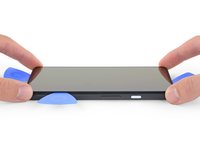
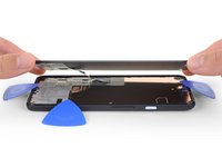
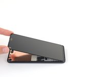
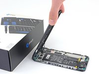
    • Lift from the top edge and swing the screen over the bottom edge until you can rest it glass-side down.
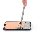
    • Be careful not to put any stress on the attached ribbon cable.

  13. Motherboard Removal, Disconnect the display: step 13, image 1 of 3 Motherboard Removal, Disconnect the display: step 13, image 2 of 3 Motherboard Removal, Disconnect the display: step 13, image 3 of 3
    • Use your fingernail or a pair of tweezers to carefully peel off the tape covering the screen connector.
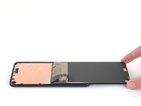
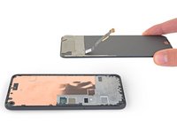
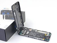
    • If it is in good condition, you can re-use this tape during reassembly. Otherwise, replace it with a piece of Kapton tape.

  14. Motherboard Removal: step 14, image 1 of 3 Motherboard Removal: step 14, image 2 of 3 Motherboard Removal: step 14, image 3 of 3
    • Insert the tip of a spudger into the opening of the plastic cover securing the screen flex cable.

    • Pry the plastic cover straight up until it pops out of place.

    • The plastic cover may spring into the air.

    • Remove the plastic cover.

  15. Motherboard Removal: step 15, image 1 of 2 Motherboard Removal: step 15, image 2 of 2
    • Use the tip of a spudger to pry up and disconnect the screen flex cable.

    • To re-attach press connectors like this one, carefully align and press down on one side until it clicks into place, then repeat on the other side. Do not press down on the middle. If the connector is misaligned, the pins can bend, causing permanent damage.

  16. Motherboard Removal, Remove the screen: step 16, image 1 of 3 Motherboard Removal, Remove the screen: step 16, image 2 of 3 Motherboard Removal, Remove the screen: step 16, image 3 of 3
    • Remove the screen.

    • To install a new screen:

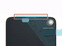
    • Check if your replacement screen has speaker mesh and top edge adhesive pre-installed.

    • If it does, you won't need the top edge adhesive.

    • If it doesn't, remove the larger clear liner from the top edge adhesive and apply it to the screen (not the frame). Make sure the larger cutout lines up with the speaker mesh.

    • Follow this guide to apply the custom-cut adhesive.

    • Use the third photo as a reference to position your adhesives.

    • During the boot-up process after reassembly, the screen will go through a calibration sequence. Don't touch the screen during this process, as it could result in improper touch calibration and create touch issues.

  17. Motherboard Removal, Remove the midframe screws: step 17, image 1 of 2 Motherboard Removal, Remove the midframe screws: step 17, image 2 of 2
    Tool used on this step:
    Magnetic Project Mat
    $19.95
    Buy
    • Use a T3 Torx driver to remove the nine 4.4 mm-long screws securing the back cover to the midframe.

    • Throughout this repair, keep track of each screw and make sure it goes back exactly where it came from.

  18. Motherboard Removal, Separate the back cover from the midframe: step 18, image 1 of 3 Motherboard Removal, Separate the back cover from the midframe: step 18, image 2 of 3 Motherboard Removal, Separate the back cover from the midframe: step 18, image 3 of 3
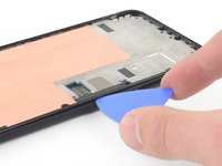
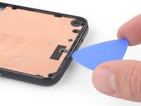
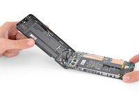
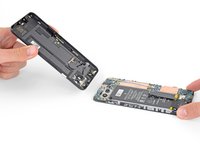
    • Insert an opening pick into the seam between the midframe and the back cover, right above the SIM card slot.

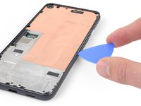
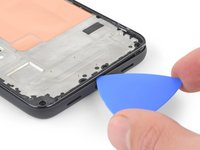
    • Slide the opening pick along the right edge of your phone to release the plastic clips securing the back cover to the midframe.

  19. Motherboard Removal: step 19, image 1 of 3 Motherboard Removal: step 19, image 2 of 3 Motherboard Removal: step 19, image 3 of 3
    • Continue sliding the opening pick along the top, left, and bottom edges of your phone until all of the plastic tabs securing the back cover to the midframe are released.

  20. Motherboard Removal: step 20, image 1 of 3 Motherboard Removal: step 20, image 2 of 3 Motherboard Removal: step 20, image 3 of 3
    • Flip your phone over so the back cover is facing up.

    • Carefully swing the back cover up to an upright position.

    • Do not remove the back cover. It is still attached by two ribbon cables.

    • Rest the back cover against an object such as a cardboard box or soda can.

  21. Motherboard Removal, Remove the motherboard bracket: step 21, image 1 of 2 Motherboard Removal, Remove the motherboard bracket: step 21, image 2 of 2
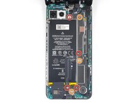
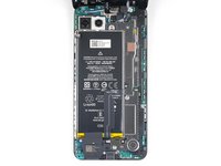
    • Use a T3 Torx screwdriver to remove the seven screws securing the motherboard bracket:

    • Four 4.0 mm-long screws

    • Three 2.1 mm-long screws

  22. Motherboard Removal: step 22, image 1 of 2 Motherboard Removal: step 22, image 2 of 2
    • Remove the motherboard bracket.

  23. Motherboard Removal, Disconnect the battery: step 23, image 1 of 2 Motherboard Removal, Disconnect the battery: step 23, image 2 of 2
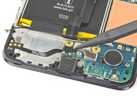
    • Use the tip of a spudger to disconnect the battery cable from the motherboard.

  24. Motherboard Removal, Remove the back cover: step 24, image 1 of 2 Motherboard Removal, Remove the back cover: step 24, image 2 of 2
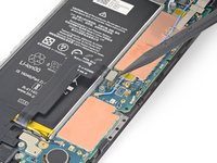
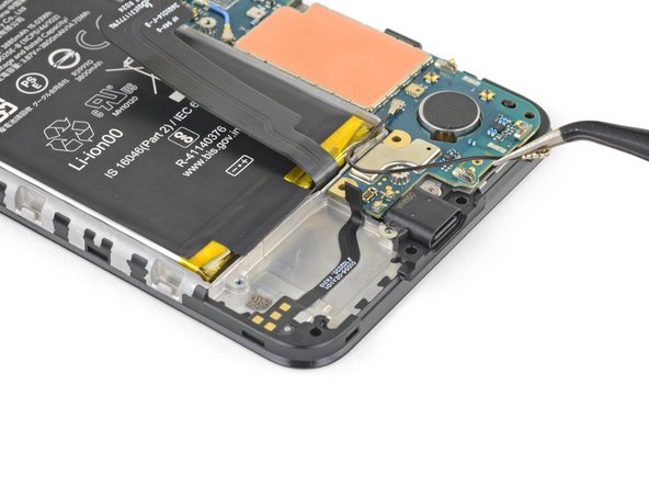
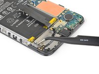
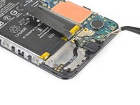
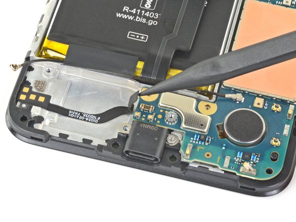
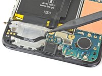
    • Use the tip of a spudger to pry up and disconnect the fingerprint sensor cable.
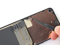
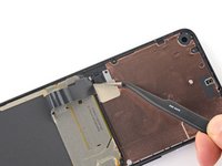
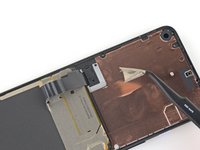
  25. Motherboard Removal: step 25, image 1 of 2 Motherboard Removal: step 25, image 2 of 2
    • Use the tip of a spudger to pry up and disconnect the front sensor array cable.

  26. Motherboard Removal: step 26, image 1 of 2 Motherboard Removal: step 26, image 2 of 2
    • Remove the back cover.

  27. Motherboard Removal, Remove the front-facing camera: step 27, image 1 of 2 Motherboard Removal, Remove the front-facing camera: step 27, image 2 of 2
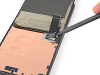
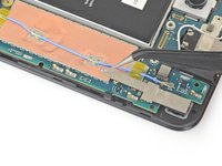
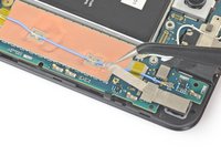
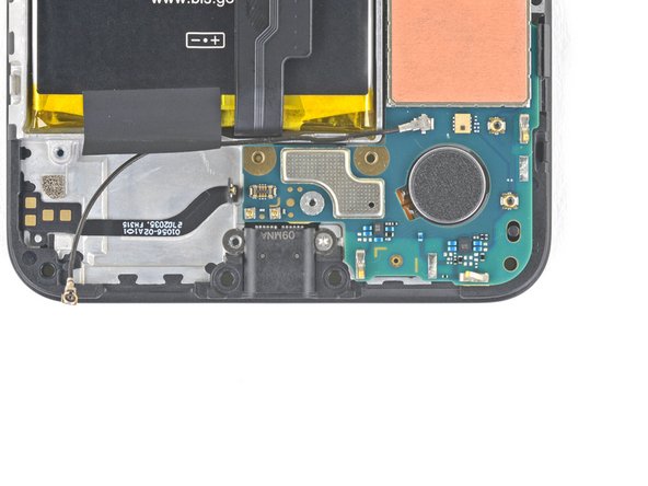
    • Use your fingers or a pair of tweezers to peel the tape off of the copper foil.

    • The copper foil is thin and easily punctured.

  28. Motherboard Removal: step 28, image 1 of 3 Motherboard Removal: step 28, image 2 of 3 Motherboard Removal: step 28, image 3 of 3
    • Use the flat end of a spudger to disconnect the front-facing camera from the motherboard.

    • Remove the front-facing camera.

  29. Motherboard Removal, Remove the loudspeaker: step 29, image 1 of 2 Motherboard Removal, Remove the loudspeaker: step 29, image 2 of 2
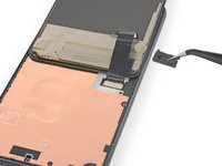
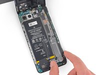
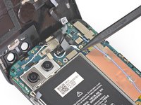
    • Use a T3 Torx driver to remove the two 4.2 mm-long screws from the loudspeaker assembly.
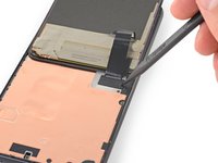
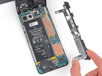
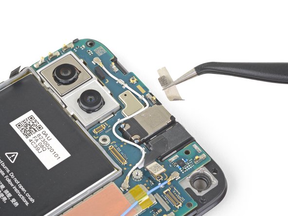
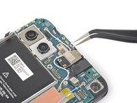
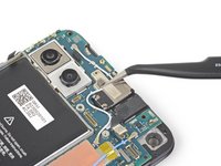
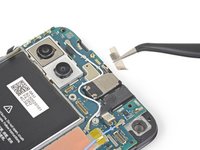
  30. Motherboard Removal: step 30, image 1 of 3 Motherboard Removal: step 30, image 2 of 3 Motherboard Removal: step 30, image 3 of 3
    • Insert the tip of a spudger underneath the loudspeaker assembly.

    • Be careful not to puncture the white membranes on either side of the loudspeaker if you are intending to reuse it.

    • Flip the loudspeaker assembly over so it lightly rests on top of the battery.

  31. Motherboard Removal: step 31, image 1 of 2 Motherboard Removal: step 31, image 2 of 2
    • Use a pair of tweezers to disconnect the antenna cable from the loudspeaker assembly.

    • Grab the metal connector of the antenna cable with your tweezers—not the plastic cable.

  32. Motherboard Removal: step 32, image 1 of 3 Motherboard Removal: step 32, image 2 of 3 Motherboard Removal: step 32, image 3 of 3
    • Carefully peel the loudspeaker assembly up off the tape underneath it.

    • Be careful not to puncture the white membranes on either side of the loudspeaker if you are intending to reuse it.

    • Remove the loudspeaker assembly.

  33. Motherboard Removal, De-route the antenna flex cable: step 33, image 1 of 3 Motherboard Removal, De-route the antenna flex cable: step 33, image 2 of 3 Motherboard Removal, De-route the antenna flex cable: step 33, image 3 of 3
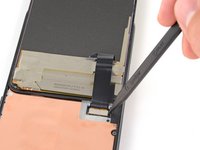
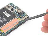
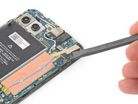
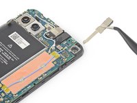
    • Use your fingers or a pair of tweezers to pull the antenna cable out from underneath the tape covering it.

  34. Motherboard Removal, Disconnect the loudspeaker cable: step 34, image 1 of 2 Motherboard Removal, Disconnect the loudspeaker cable: step 34, image 2 of 2
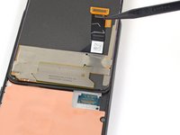
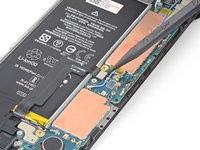
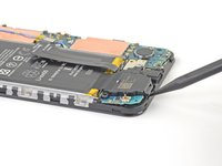
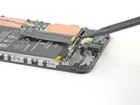
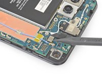
    • Use the tip of a spudger to disconnect the loudspeaker cable from the motherboard.

  35. Motherboard Removal, Disconnect the headphone jack: step 35, image 1 of 2 Motherboard Removal, Disconnect the headphone jack: step 35, image 2 of 2
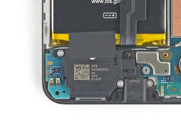
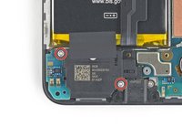
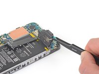
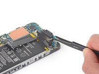
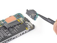
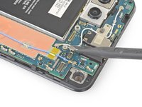
    • Use the tip of a spudger to disconnect the headphone jack cable from the motherboard.

  36. Motherboard Removal: step 36, image 1 of 3 Motherboard Removal: step 36, image 2 of 3 Motherboard Removal: step 36, image 3 of 3
    • Use a pair of tweezers to remove the tape on the earpiece speaker covering the antenna flex cable.

  37. Motherboard Removal, Remove the charging port screw: step 37, image 1 of 2 Motherboard Removal, Remove the charging port screw: step 37, image 2 of 2
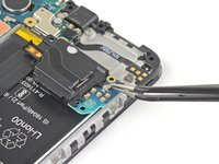
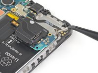
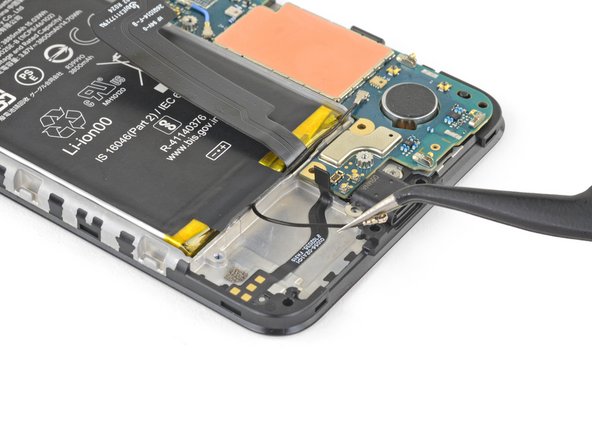
    • Use a T3 Torx screwdriver to remove the 2.1 mm-long screw securing the charging port.

  38. Motherboard Removal, Remove the motherboard: step 38, image 1 of 2 Motherboard Removal, Remove the motherboard: step 38, image 2 of 2
    • The motherboard is secured to the midframe by plastic clips.

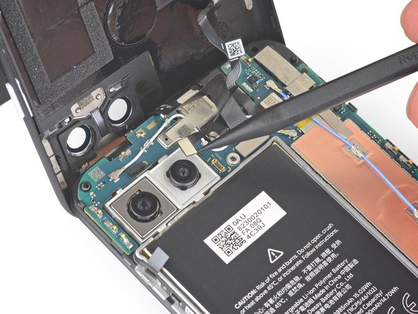
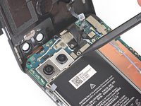
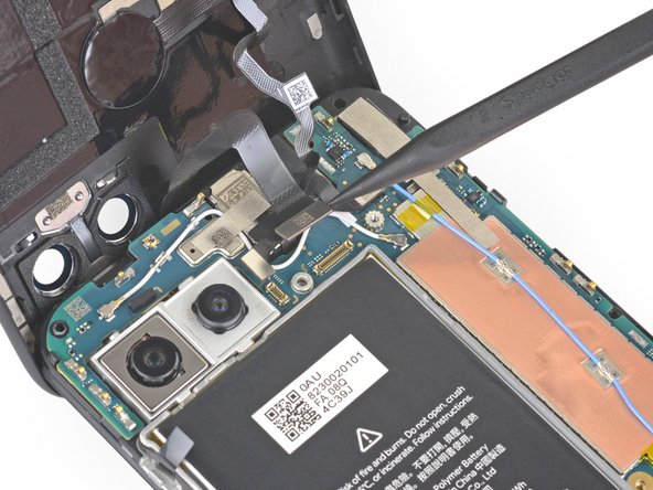
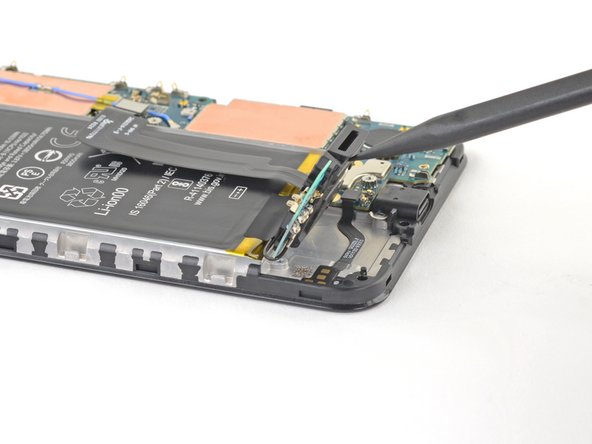
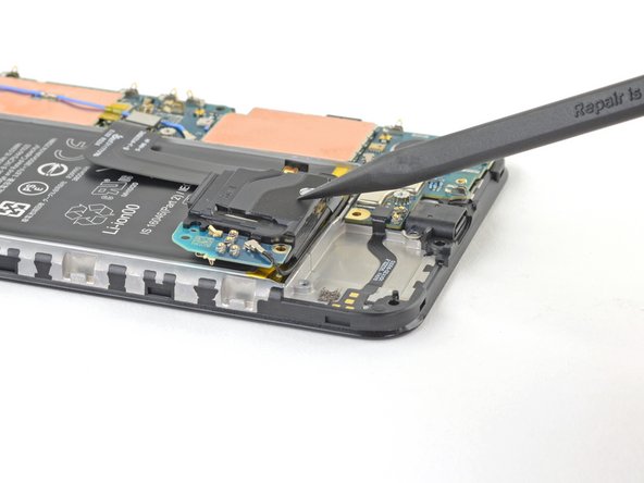
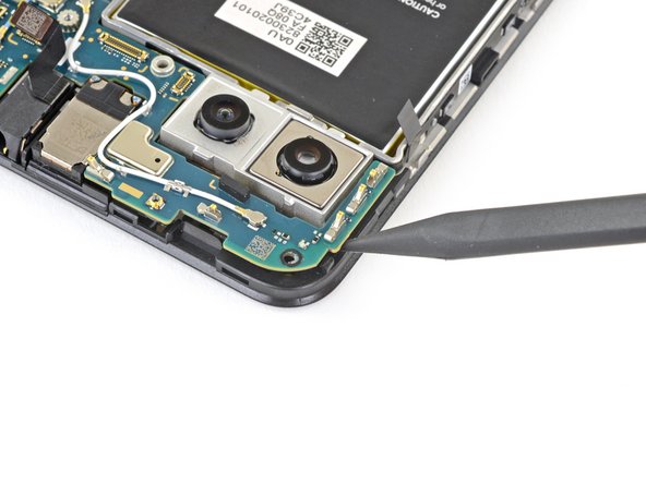
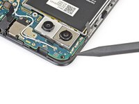
    • Insert the tip of a spudger into the gap between the motherboard and the midframe near the front-facing cameras to pop it free from the first clip.

  39. Motherboard Removal: step 39, image 1 of 3 Motherboard Removal: step 39, image 2 of 3 Motherboard Removal: step 39, image 3 of 3
    • Grab the motherboard with your fingers and open it like a book.

    • This will release the rest of the clips.

    • Lift the motherboard straight out to remove it.

Conclusion

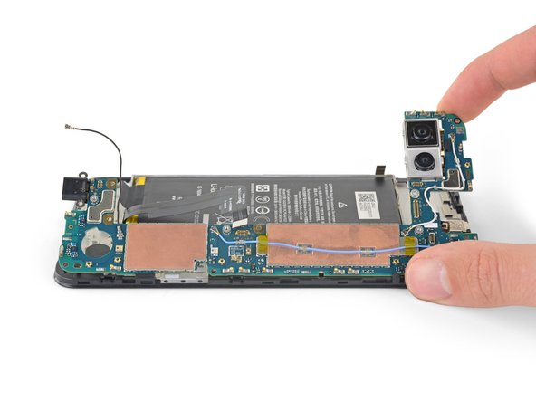
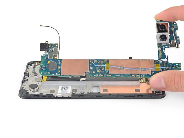
To reassemble your device, follow these instructions in reverse order.

Sam Omiotek

Member since: 02/25/19

72,896 Reputation

288 Guides authored

0 Comments

Add Comment

View Statistics:

Past 24 Hours: 0

Past 7 Days: 0

Past 30 Days: 0

All Time: 22