Introduction
This guide will go over how to remove the motherboard on the Microsoft Surface Pro 5. Since the motherboard is the central part of the tablet computer, it takes some work to get to it. The iOpener is used in this guide, but a hair dryer or heat gun could also be used. See instructions for the iOpener here.
What you need
-
-
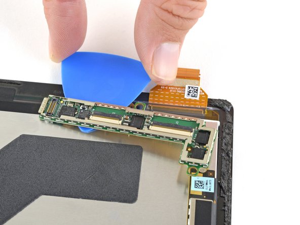
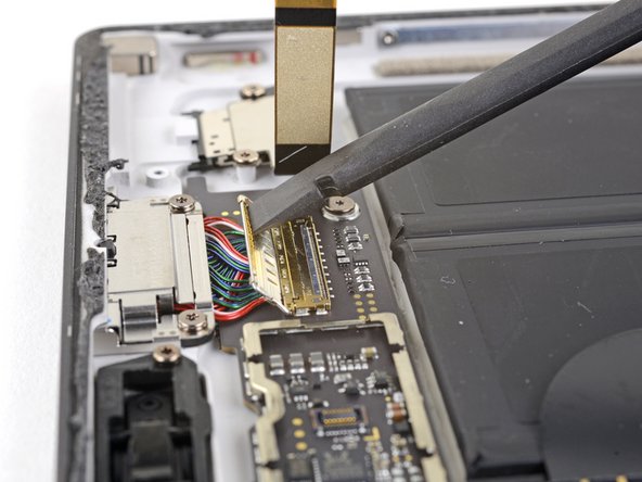
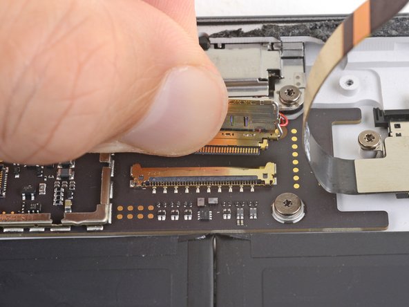
Use a spudger to flip up the small locking flaps on the display cable ZIF connectors.
-
-
-
Slide an opening pick under the display board to separate the adhesive holding it onto the back of the screen.
-
-
-
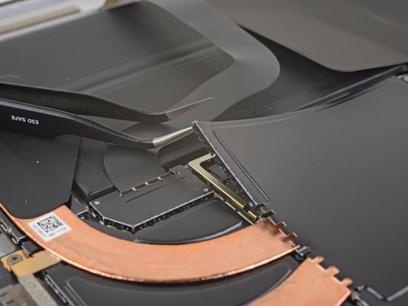
Insert one point of a pair of pointed tweezers into a gap in the corner of the EMI shield covering the heat sink.
-
Use the tweezers to pry the EMI shield away from the motherboard as much as you can without bending it. Do not remove it yet.
-
-
-
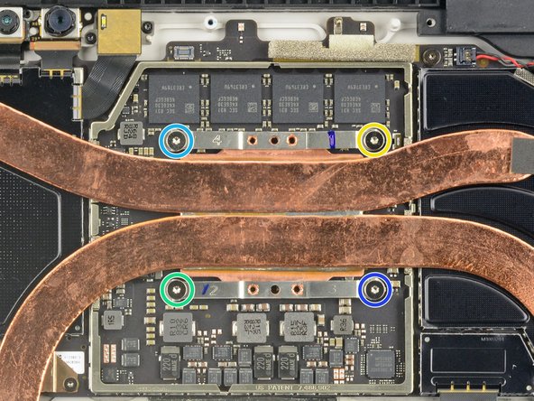
Remove the ten Torx screws securing the heat sink:
-
Five 2.6 mm-long T3 screws
-
Four 3.3 mm-long T5 screws
-
Screw 1
-
Screw 2
-
Screw 3
-
Screw 4
-
-
-
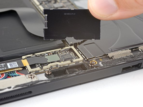
Pry off the metal cover covering the front and rear camera ribbon cable motherboard connections using a nylon spudger.
-
-
-
-
Insert one point of a pair of pointed tweezers into a gap in the corner of the EMI shield covering the microSD card reader connector.
-
Use the tweezers to pry the EMI shield away from the motherboard as much as you can without bending it.
-
Repeat this procedure at different points around the shield until it is free. Remove the shield.
-
-
-
Use the flat end of a spudger to pry the microSD card reader connector up and out of its socket on the motherboard.
-
-
-
Use the flat end of a spudger to lift the flap that sits over the SurfaceConnect port connector.
-
-
-
Use a T5 Torx driver to remove the two 3.7 mm screws securing the SurfaceConnect port.
-
-
-
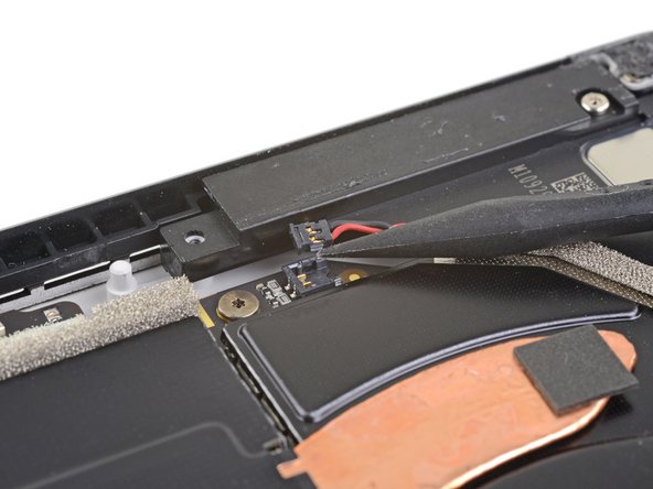
Use the point of a spudger to lift the right speaker connector up and out of its socket on the motherboard.
-
-
-
Use a T5 Torx driver to remove the two screws securing the speaker:
-
One 6 mm screw
-
One 3.7 mm screw
-
-
-
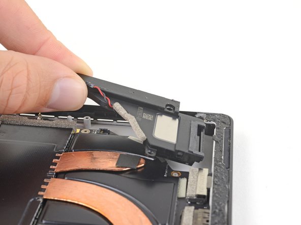
Use a spudger to lift the left edge of the speaker so that it clears the components around the speaker.
-
With the left edge lifted, slide the speaker to the left, straight out of its recess in the case.
-
-
-
Remove the Torx T5 x 6mm screw connecting the black tie bar to the power button/volume control/speaker assembly.
-
-
-
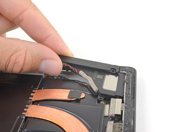
Use the plastic opening tool to pop up the connector going from the edge of the case to the motherboard.
-
Use a Torx T3 to remove the one 2.5 mm screw on the motherboard.
-


Team

Cal Poly, Team S15-G3, Livingston Fall 2017 Member of Cal Poly, Team S15-G3, Livingston Fall 2017
CPSU-LIVINGSTON-F17S15G3
3 Members
17 Guides authored