This guide has more recent changes. Switch to the latest unverified version.
Introduction
This guide shows how to remove the main board. This is required before replacing the liquid metal.
What you need
-
-
Shut down your console and unplug all cables and accessories.
-
Remove any stands supporting your device and lay it down.
-
-
-
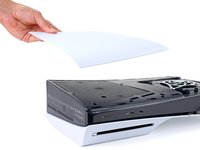
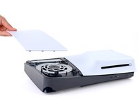
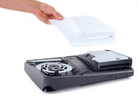
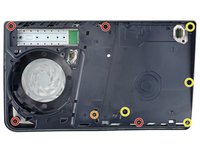
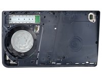
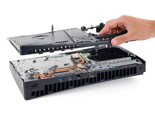
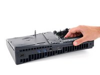
To remove a cover, firmly pull up the front edge to release the clips.
-
Remove the cover.
-
-
-
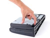
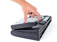
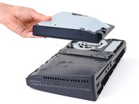
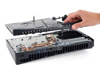
Use the cutout on the bottom right corner of the disc drive to lift its right edge and disconnect it.
-
Remove the disc drive.
-
-
Tool used on this step:FixMat$36.95
-
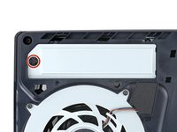
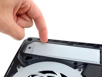
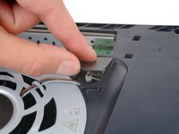
Use a Phillips screwdriver to remove the 17.1 mm‑long screw securing the expansion slot cover.
-
-
-
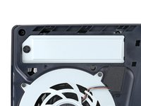
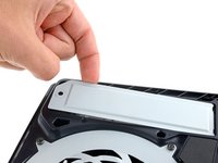
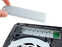
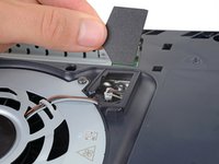
Use your fingers to lift the expansion slot cover near the notch by the screw hole and remove it.
-
-
Tool used on this step:Tesa 61395 Tape$8.95
-
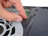
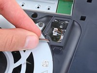
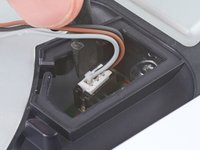
Use your fingers to remove the plastic cover hiding the fan cables connector.
-
-
-
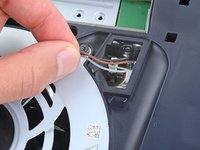
Gently pull the fan cables out from under their plastic clip on the frame.
-
-
-
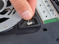
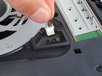
Firmly grip the fan cables white connector head and pull it straight up and out of its socket.
-
-
-
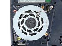
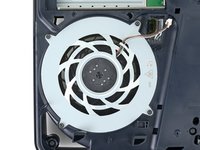
Use a T8 Torx Security screwdriver to remove the four screws securing the fan:
-
One 31.2 mm‑long screw
-
Two 21.3 mm‑long screws
-
One 11.6 mm‑long screw
-
-
-
-
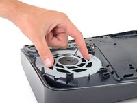
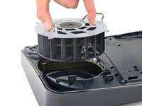
Use your fingers to grab the fan by its vents, and lift it straight up to remove it.
-
Insert the fan so its cables are near their connector.
-
-
Tool used on this step:Tweezers$4.99
-
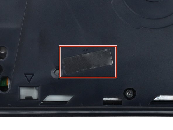
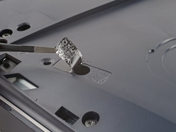
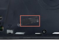
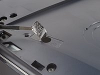
A tamper-evident sticker hides one of the main board cover screws.
-
Use tweezers to peel up the sticker up until you can access the screw underneath.
-
-
-
Use a T8 Torx Security screwdriver to remove the nine screws securing the main board cover:
-
Four 18.9 mm‑long screws
-
One 21.3 mm‑long screw
-
Four 31.2 mm‑long screws
-
-
-
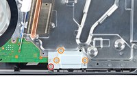
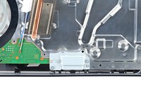
Use a T8 Torx Security screwdriver to remove the four screws securing the interconnect cable cover:
-
One 28.7 mm‑long screw
-
Three 7.5 mm‑long screws
-
-
-
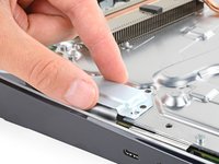
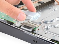
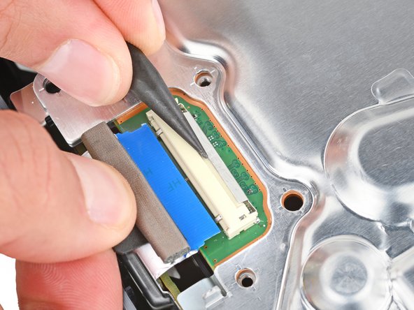
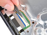
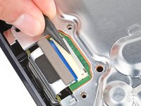
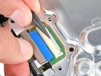
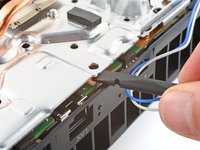
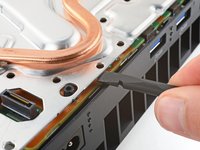
Use the point of a spudger to push the interconnect cable's metal latch down and away from the connector to unlock it.
-
Keep the latch in its unlocked position and carefully pull the interconnect cable straight out of its socket.
-
-
-
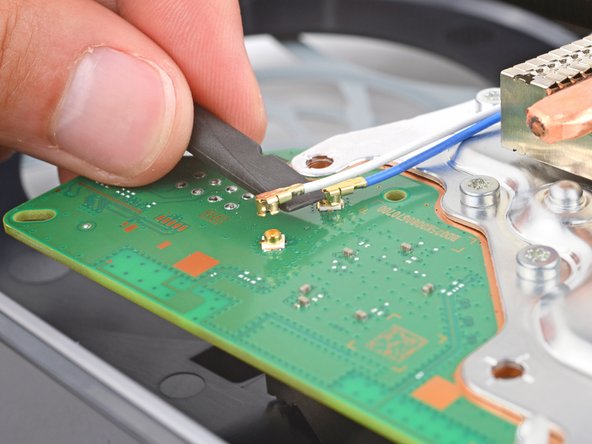
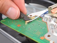
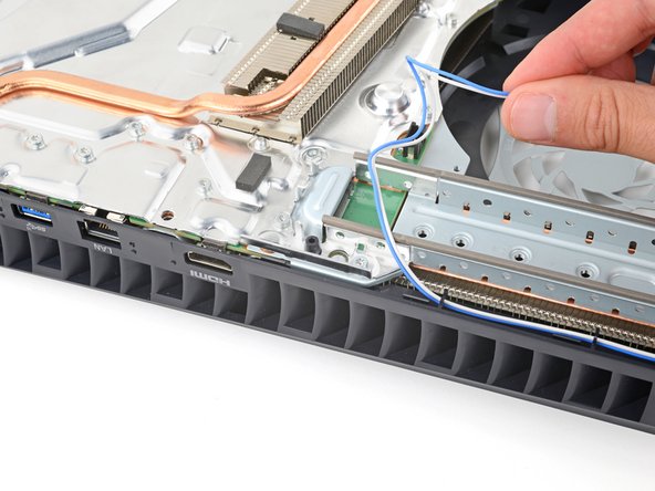
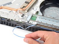
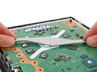
Insert the flat end of a spudger under the metal neck of one of the antenna cable's coaxial connectors and lift straight up to disconnect it.
-
Repeat the process to disconnect the other antenna cable.
-
-
-
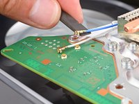
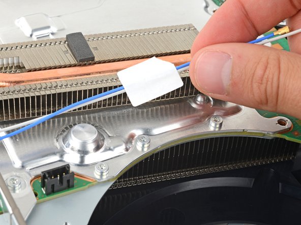
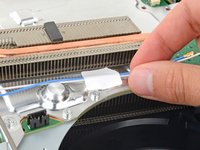
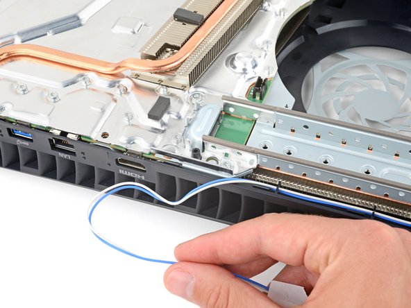
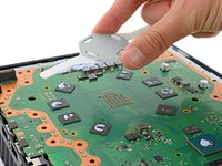
Gently lift both antenna cables to separate the tape from the heatsink shield.
-
-
-
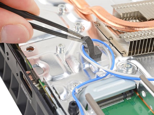
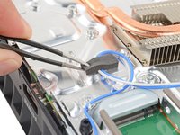
Move the antenna cables over the side of your PlayStation so they're out of the way.
-
-
-
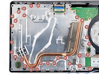
Use a T8 Torx Security screwdriver to remove the thirty 7.5 mm‑long screws securing the top shield plate.
-
-
-
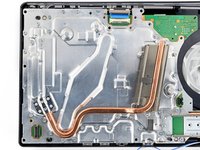
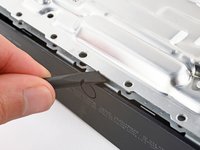
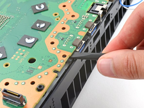
Insert the flat end of a spudger between the top shield plate and the main board and pry up to release the plate. Work your way around the perimeter until it separates completely.
-
-
-
Use a T8 Torx Security screwdriver to remove the four remaining screws securing the main board:
-
Two 7.5 mm‑long main board screws
-
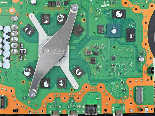
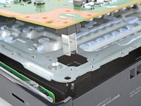
Two 16.3 mm‑long screws securing the APU tension bracket
-
-
-
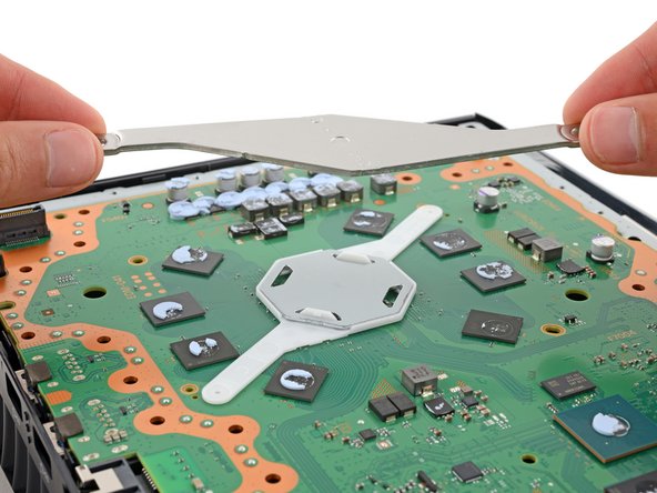
Lift and remove both APU brackets from the board.
-
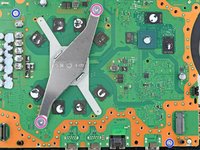
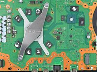
Put the bracket with plastic arms on first so the pegs go into their cutouts.
-
Then, put the metal bracket onto the plastic one so they're perpendicular and the screw holes line up.
-
-
-
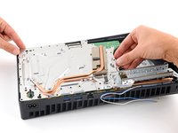
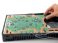
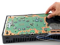
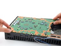
Gently lift the edge of the motherboard with the large cutout to partially separate it from the bottom shield plate.
-
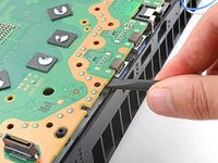
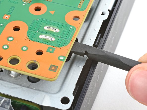
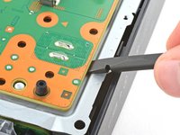
With the board lifted, insert the flat end of a spudger between the board and the bottom shield plate and gently twist to separate them. Work your way around the perimeter of the board.
-
-
-
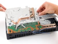
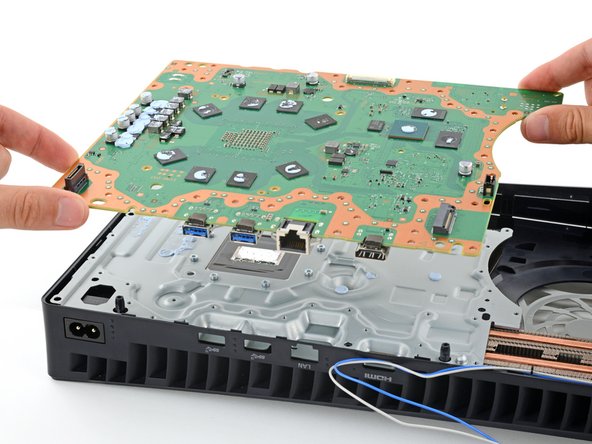
Remove the main board, flip it over, and carefully lay it on a clean work surface, so the APU is facing up.
-
Make sure all cables that connect to the board are out of the way so they don't get trapped underneath.
-
Carefully flip the board over so the APU is on the bottom, making sure no liquid metal spills.
-
Keep the board level and lower it into place.
-


To reassemble your device, follow these instructions in reverse order.

