Introduction
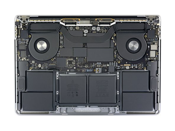
Prerequisite only—use this guide to remove the logic board and heat sink together on the way to making repairs.
What you need
-
-
Power on your Mac and launch Terminal.
-
Copy and paste the following command (or type it exactly) into Terminal:
-
sudo nvram AutoBoot=%00
-
Press [return]. If prompted, enter your administrator password and press [return] again. Note: Your return key may also be labeled ⏎ or "enter."
-
sudo nvram AutoBoot=%03
-
-
-
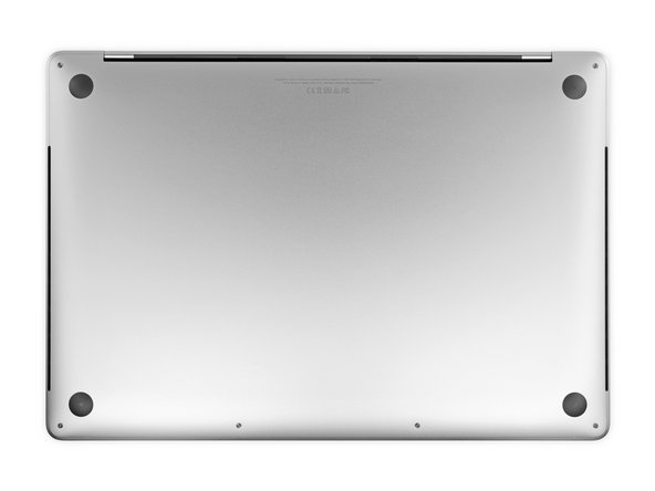
Use a P5 Pentalobe driver to remove six screws securing the lower case, of the following lengths:
-
Four 3.7 mm screws
-
Two 7.3 mm screws
-
-
-
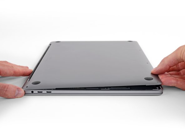
Press a suction handle into place near the front edge of the lower case, between the screw holes.
-
Pull up on the suction handle just enough to open a small gap under the lower case.
-
-
-
Remove the lower case.
-
Set it in place and align the sliding clips near the display hinge. Press down and slide the cover toward the hinge. It should stop sliding as the clips engage.
-
When the sliding clips are fully engaged and the lower case looks correctly aligned, press down firmly on the lower case to engage the four hidden clips underneath. You should feel and hear them snap into place.
-
-
-
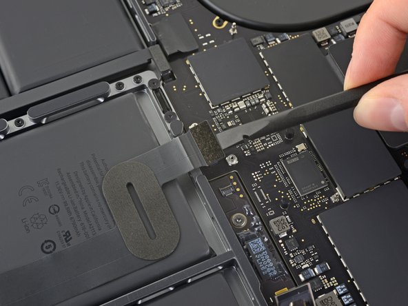
Peel up and remove the insulating sticker covering the battery board, on the edge of the logic board nearest the battery.
-
If the cover doesn't peel up easily, apply mild heat with an iOpener, hair dryer, or heat gun to soften the adhesive underneath, and try again.
-
-
-
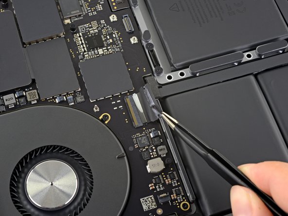
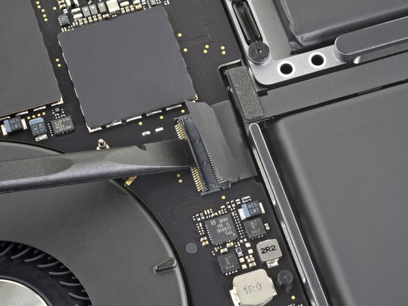
Use a spudger to gently pry up the locking flap on the ZIF connector for the battery board data cable.
-
-
-
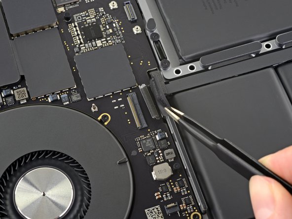
Slide the battery board data cable out of its socket on the battery board, and remove it completely.
-
-
-
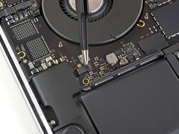
Use a T5 Torx driver to remove the 6.7 mm pancake screw securing the battery power connector.
-
-
-
Use a T3 Torx driver to remove the two 1.8 mm screws securing the cover bracket for the keyboard and trackpad cable connectors.
-
Remove the bracket.
-
-
-
Use a spudger to disconnect the trackpad cable by prying its connector straight up from the logic board.
-
-
-
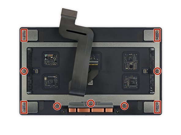
Use a T5 Torx driver to remove the 13 screws securing the trackpad assembly:
-
Nine 5.8 mm screws
-
Four 4.9 mm screws
-
-
-
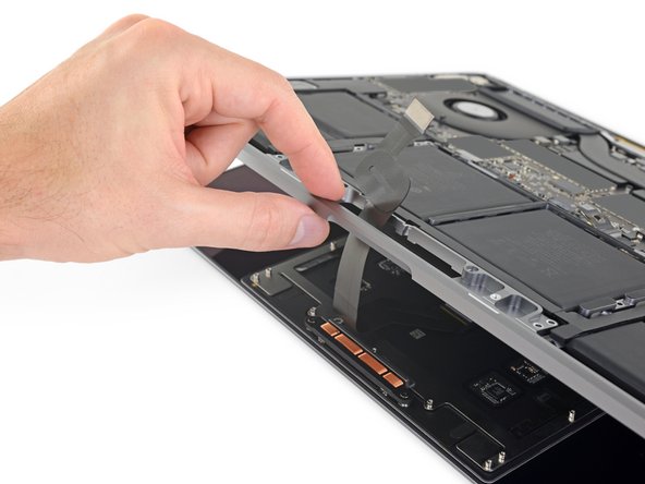
Swing the display open slightly, but keep the MacBook upside-down. The trackpad assembly should separate and lay flat on the display.
-
Carefully feed the trackpad's ribbon cable through its slot in the chassis.
-
-
-
-
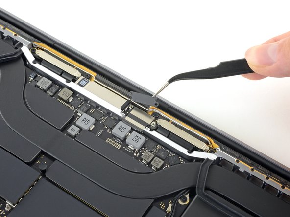
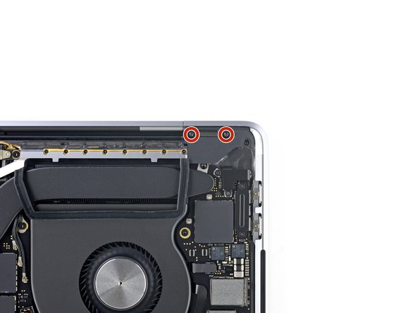
Use a T3 Torx driver to remove the two 3.5 mm screws securing the cover on the display board flex cable.
-
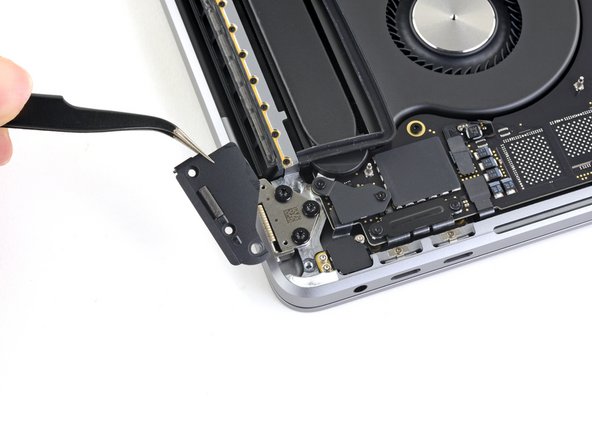
Remove the display board flex cover.
-
-
-
Use a T3 Torx driver to remove the four 2.0 mm screws from the hinge covers (two screws on each side).
-
-
-
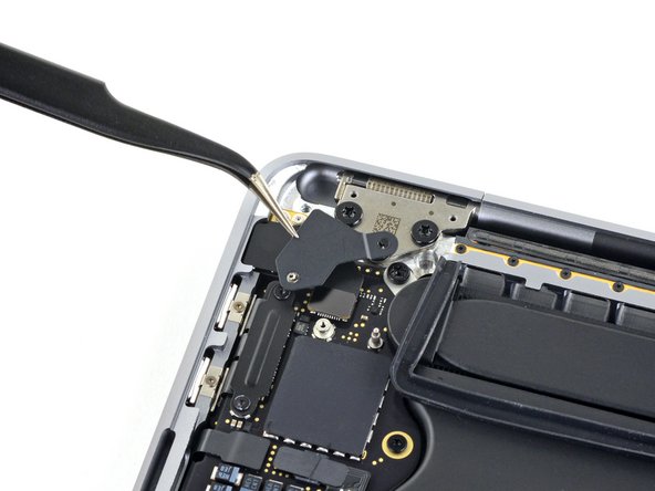
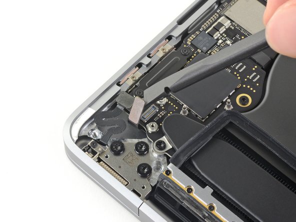
Use a T3 Torx driver to remove the two 2.4 mm screws securing the cover bracket for the Touch ID and headphone jack cable connectors.
-
Remove the bracket.
-
-
-
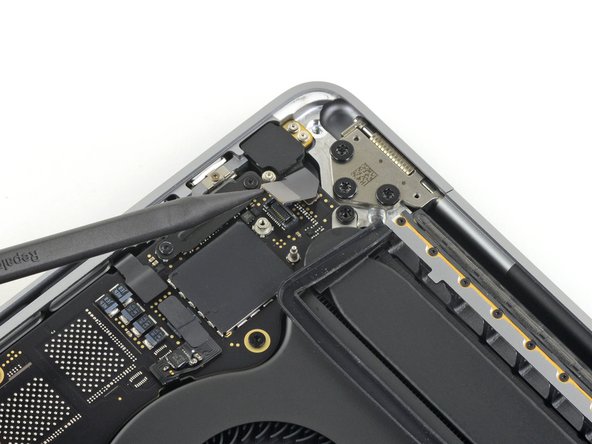
Using a T3 Torx driver, remove the two 1.5 mm screws securing the cover bracket for the Touch Bar digitizer and lid angle sensor connectors.
-
-
-
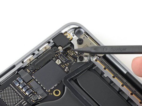
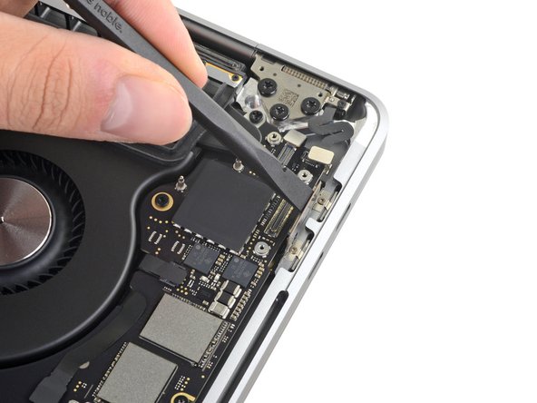
Use a T3 Torx driver to remove the two 1.9 mm screws securing the bracket for the Touch Bar display cable connector.
-
Remove the bracket.
-
-
-
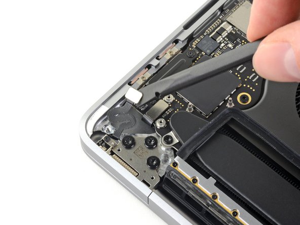
Using a T3 Torx Driver:
-
Remove the two 1.3 mm screws securing the Thunderbolt flex cable cover on the left.
-
Remove two more 1.3 mm screws from the Thunderbolt cable cover on the right.
-
-
-
Peel back the tape covering the keyboard cable connector.
-
-
-
Use a spudger to gently pry straight up on the long locking flap on the ZIF connector for the keyboard cable.
-
-
-
Peel back any tape covering the left speaker cable connector.
-
-
-
Peel back any tape covering the right speaker cable connector.
-
-
-
Peel back any tape covering the first keyboard backlight cable connector.
-
-
-
Disconnect the keyboard backlight by pulling its cable away from the logic board until it releases from its socket.
-
If possible, pull on the tape attached to the cable, rather than the cable itself, to reduce the risk of damage.
-
Move the cable away from its connector so it can more easily clear the logic board during removal.
-
-
-
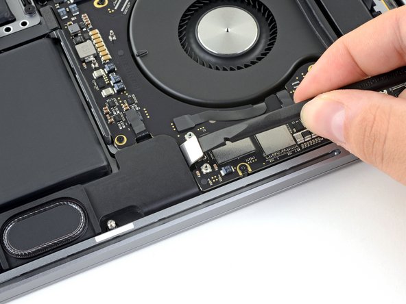
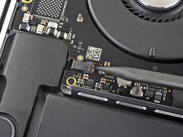
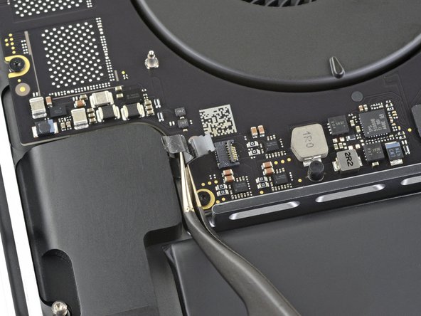
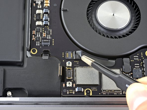
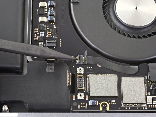
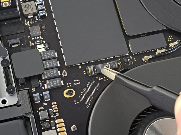
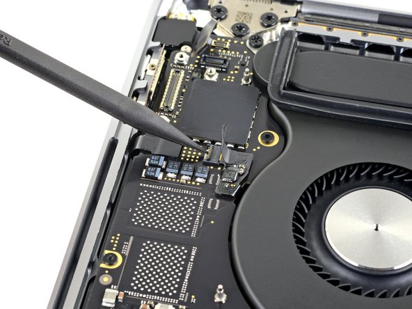
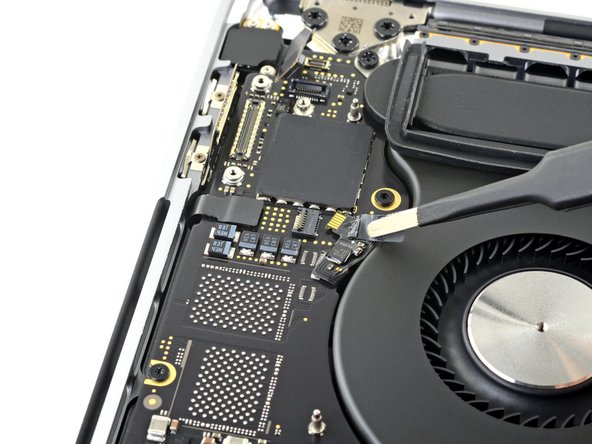
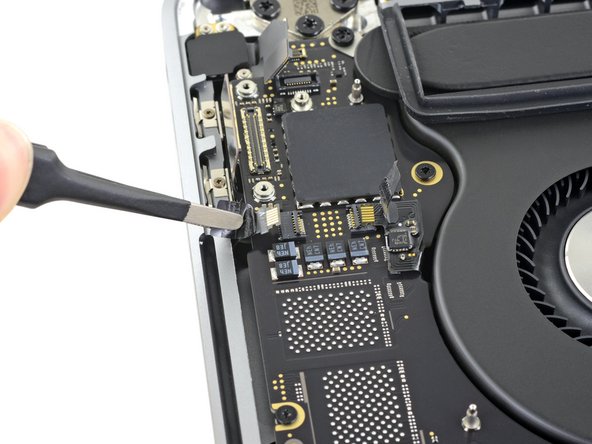
Open the locking flap on the right fan's ZIF connector by prying it straight up from the logic board.
-
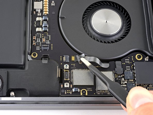
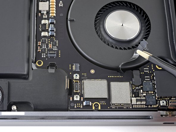
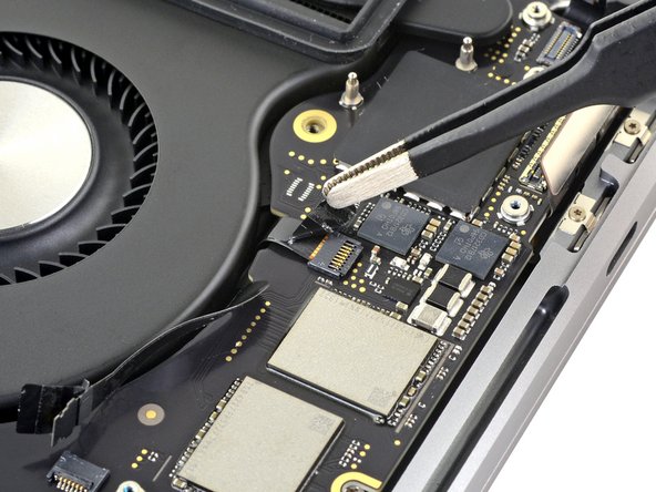
Disconnect the right fan by pulling its cable away from the logic board until it releases from its socket.
-
If possible, pull on the tape attached to the cable, rather than the cable itself, to reduce the risk of damage.
-
-
-
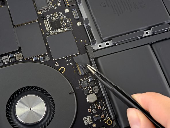
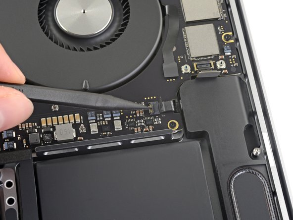
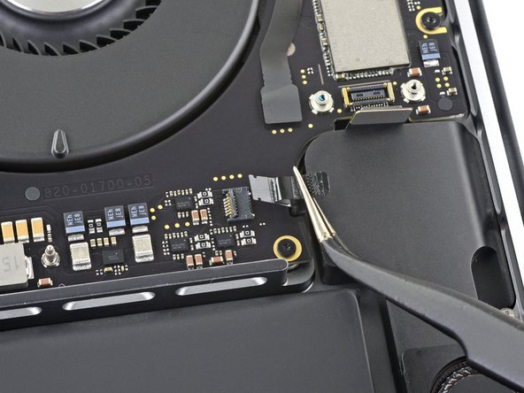
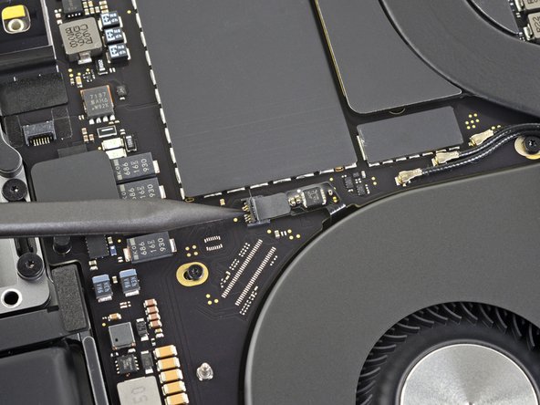
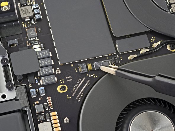
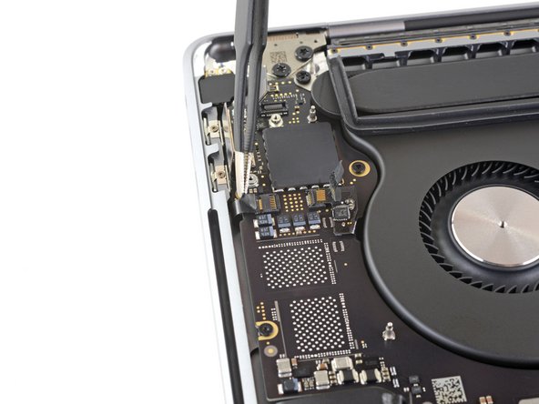
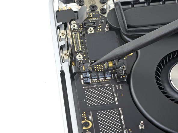
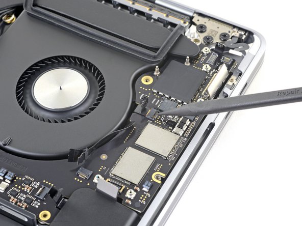
Open the locking flap on the left fan's ZIF connector by prying it straight up from the logic board.
-
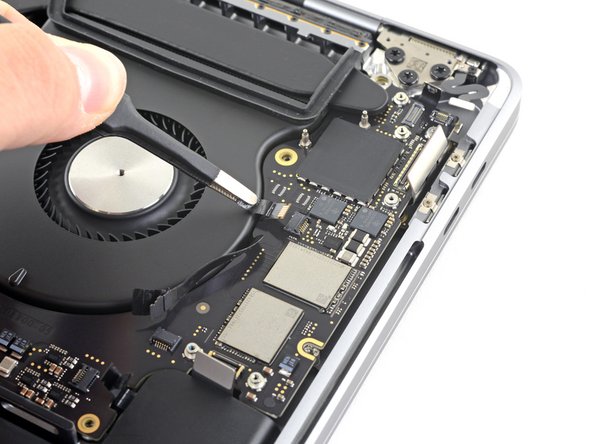
Disconnect the left fan by pulling its cable away from the logic board until it releases from its socket.
-
If possible, pull on the tape attached to the cable, rather than the cable itself, to reduce the risk of damage.
-
-
-
Peel back any tape covering the other keyboard backlight connector.
-
-
-
Open the locking flap on the keyboard backlight's ZIF connector by prying it straight up from the logic board.
-
Disconnect the keyboard backlight by pulling its cable away from the logic board until it releases from its socket.
-
If possible, pull on the tape attached to the cable, rather than the cable itself, to reduce the risk of damage.
-
-
-
Peel back any tape covering the microphone array connector.
-
-
-
Open the locking flap on the microphone array's ZIF connector by prying it straight up from the logic board.
-
Disconnect the microphone array by pulling its cable away from the logic board until it releases from its socket.
-
If possible, pull on the tape attached to the cable, rather than the cable itself, to reduce the risk of damage.
-
-
-
Use a T5 Torx driver to remove the single 2.9 mm screw securing the antenna cable bundle.
-
-
-
Remove all eleven screws securing the logic board assembly:
-
Three 3.3 mm T3 Torx screws
-
Two 3.6 mm T5 Torx screws
-
Four 2.9 mm T5 Torx screws
-
One 4.0 mm T8 Torx screw
-
One 4.0 mm T8 Torx screw (large head)
-
-
-
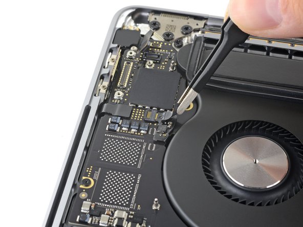
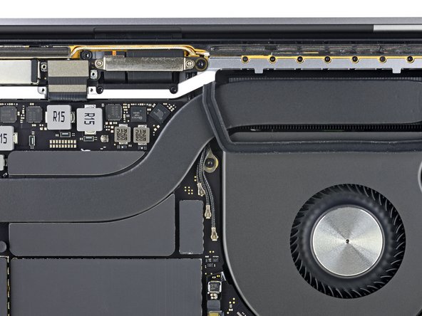
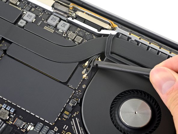
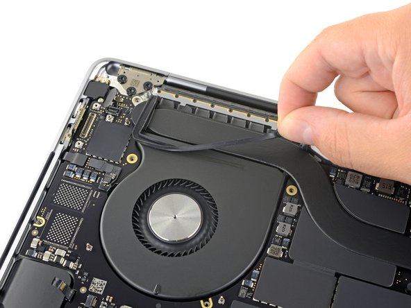
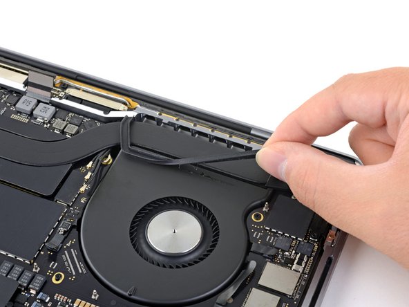
Peel up (but don't remove) the rubber vibration damping strip from the adhesive holding it to the fan.
-
If needed, apply mild heat with an iOpener, hair dryer, or heat gun to soften the adhesive and make the dampers easier to separate.
-
Repeat for the other adhesive strip on the opposite fan.
-


To reassemble your device, follow these instructions in reverse order.
To reassemble your device, follow these instructions in reverse order.

