Introduction
Use this guide to replace the trackpad. This procedure involves using adhesive remover to remove the battery. Do not reuse the battery after it has been removed, as doing so is a potential safety hazard. Replace it with a new battery.
iFixit adhesive remover is highly flammable. Perform this procedure in a well-ventilated area. Do not smoke or work near an open flame during this procedure.
To minimize risk of damage, turn on your MacBook and allow the battery to fully discharge before starting this procedure. A charged lithium-ion battery can create a dangerous and uncontrollable fire if accidentally punctured. If your battery is swollen, take extra precautions.
What you need
-
Tool used on this step:Magnetic Project Mat$19.95
-
Remove the following ten screws securing the lower case to the upper case:
-
Two 2.3 mm P5 Pentalobe screws
-
Eight 3.0 mm P5 Pentalobe screws
 Ask FixBot
-
-
-
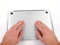
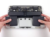
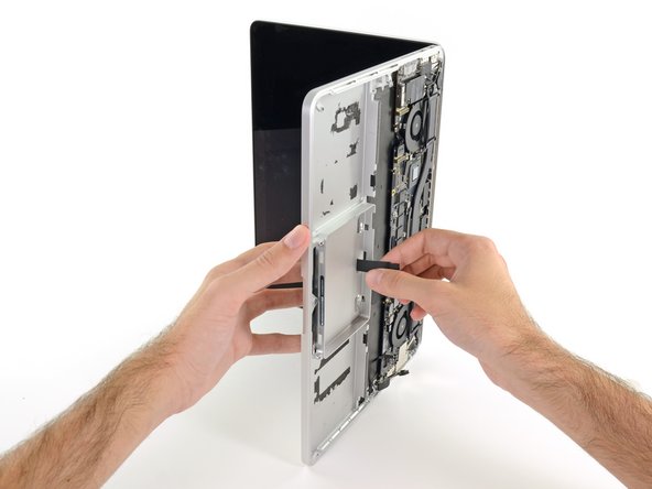
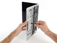
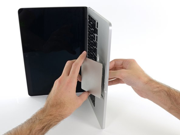
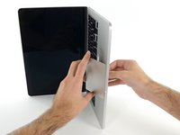
Wedge your fingers between the upper case and the lower case.
-
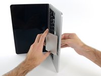
Gently pull the lower case away from the upper case.
-
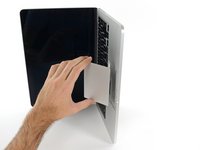
Remove the lower case and set it aside.
-
-
-
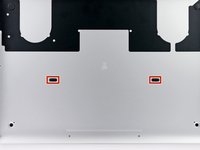
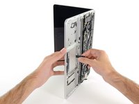
The lower case is connected to the upper case at the center, with two plastic clips.
-
-
-
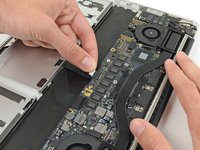
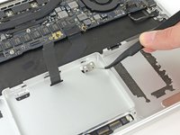
Remove the plastic cover adhered to the battery contact board.
-
-
-
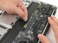
Remove the following screws securing the battery connector board to the logic board:
-
Two 2.8 mm T6 Torx screws
-
One 7.0 mm T6 Torx shouldered screw
-
-
Tool used on this step:Tweezers$4.99
-
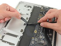
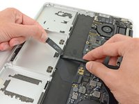
Use tweezers to remove the small plastic cover located near the bottom right of the battery connector board.
-
-
-
Remove the wide head 6.4 mm T6 Torx screw securing the battery connector to the logic board assembly.
-
-
-
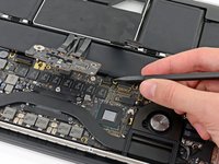
Carefully lift the battery connector board up off the logic board.
-
It is recommended to bend the battery cables just slightly, to keep the board suspended up above the logic board and out of the way.
-
-
Tool used on this step:Tweezers$4.99
-
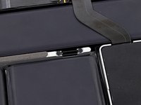
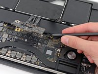
Grasp the Interposer with tweezers.
-
Lift the Interposer off the logic board and remove it.
-
-
-
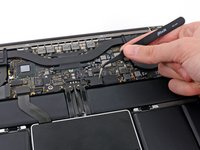
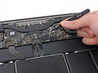
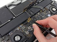
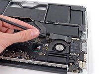
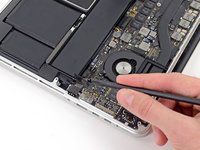
Use the flat end of a spudger to pry the right side of the I/O board data cable connector up off its socket on the I/O board.
-
-
-
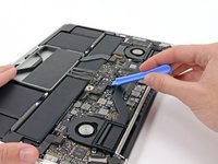
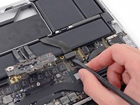
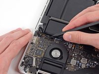
Wedge the flat end of a spudger beneath the left side of the I/O board data cable connector.
-
Gently twist the spudger to disconnect the I/O board data cable connector from its socket on the logic board.
-
-
-
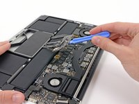
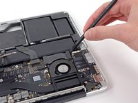
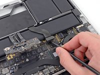
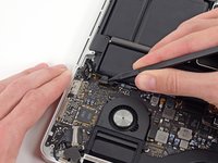
Use the flat end of a spudger to pry the SSD cable connector up from its socket on the logic board.
-
Move the SSD cable connector out of the way.
-
-
-
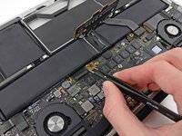
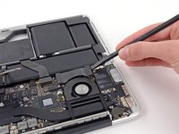
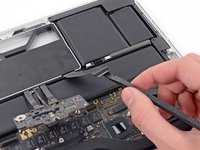
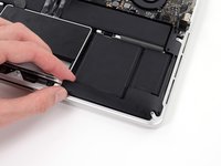
Wedge the pointed end of a spudger beneath the right speaker cable connector.
-
Gently pry the right speaker cable connector up off from its socket on the logic board.
-
-
Tool used on this step:Tweezers$4.99
-
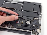
Use a T5 Torx driver to remove the following screws securing the right speaker to the upper case:
-
One black 6.8 mm screw
-
One silver 6.3 mm screw
-
One black 4.9 mm screw
-
-
-
-
Use the flat end of a spudger to pry the headphone jack cable connector straight up off its socket on the logic board.
-
-
-
Wedge the tip of a spudger beneath the left speaker cable connector.
-
Gently pry the left speaker cable connector up off from its socket on the logic board.
-
-
Tool used on this step:Tweezers$4.99
-
Use a T5 Torx driver to remove the following screws securing the left speaker to the upper case:
-
One black 6.8 mm screw
-
One silver 6.3 mm screw
-
One black 4.9 mm screw
-
-
-
Use your thumb or finger to bend the plastic spring bar on the SSD tray, freeing the two clips at the front side of the device.
-
While holding the spring bar depressed, tilt the SSD assembly up out of its cavity.
-
-
-
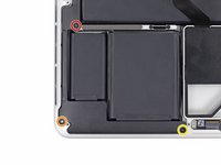
Remove three 2.2 mm T5 Torx screws from each side of the battery (six screws total).
-
-
-
To protect your display, place a sheet of aluminum foil between the display and keyboard and leave it there while you work.
-
-
-
Now that your MacBook Pro is fully prepped, it's time to prep yourself.
-
Wear eye protection when handling and applying the adhesive remover. (Eye protection is included in your kit.)
-
Do not wear contact lenses without eye protection.
-
Protective gloves are also included in your kit. If you are concerned about skin irritation, put your gloves on now.
-
-
-
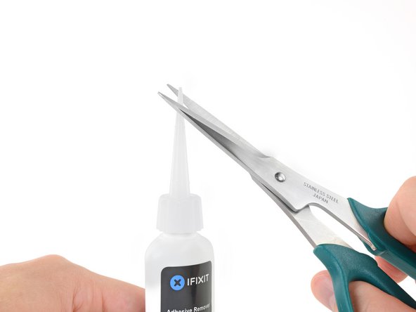
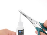
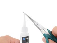
Pull off the black rubber stopper from your bottle of adhesive remover.
-
Use scissors to cut off the sealed tip of the applicator.
-
-
-
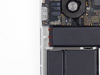
Apply a few drops of adhesive remover evenly under the edge of the leftmost battery cell.
-
Wait 2-3 minutes for the liquid adhesive remover to penetrate underneath the battery cell before you proceed to the next step.
-
-
Tool used on this step:Plastic Cards$2.99
-
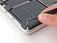
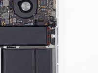
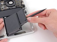
Insert the flat edge of a spudger or plastic card underneath the leftmost battery cell.
-
Run your tool along the bottom perimeter of the battery cell and lift to begin separating the adhesive.
-
-
-
Insert the spudger along the left-hand side of the leftmost battery cell.
-
Run the spudger up along the left side of the leftmost battery cell.
-
Slightly pry the leftmost battery cell to release it from the adhesive.
-
-
-
Repeat the above steps to separate the adjacent battery cell from its adhesive:
-
Apply a few drops of liquid adhesive remover under the battery cell.
-
Wait 2-3 minutes for the adhesive remover to penetrate and soften the adhesive.
-
Carefully wedge a spudger or plastic card inwards, being careful to not damage the battery, and separate the battery cell from the adhesive securing it to your MacBook Pro.
-
-
-
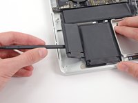
Insert the flat end of a spudger underneath the larger leftmost battery cell.
-
Carefully wedge the spudger inwards, being careful to not damage the battery cells.
-
Pry the larger leftmost battery cell up off the upper case.
-
-
-
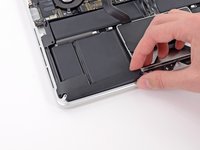
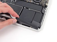
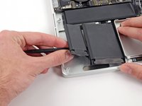
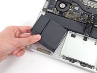
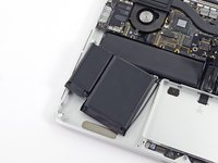
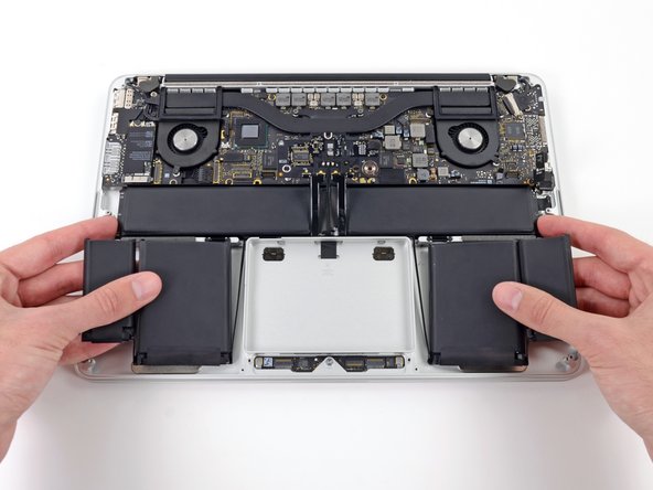
Grasp the battery cells and gently move (but do not remove) them from their recess in the upper case.
-
Leave the battery cells resting on top of the upper case as shown in the third picture.
-
-
-
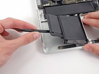
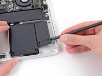
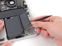
Switch sides and repeat the above procedure for the two battery cells on the right-hand side of the MacBook Pro.
-
Remember to add a small amount of liquid adhesive remover under each battery cell, and wait 2-3 minutes for it to penetrate before prying up the cell.
-
-
-
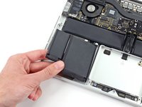
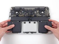
Lift the battery as a whole up out of the upper case, and remove the battery.
-
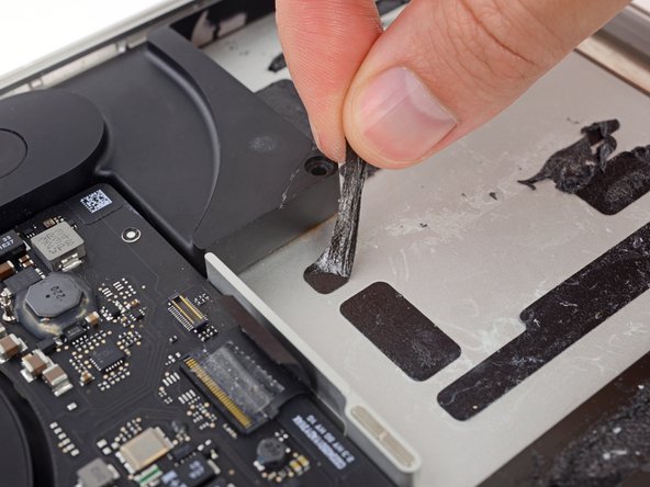
With a little luck, you can slowly pull out each strip of adhesive with your fingers.
-
Otherwise, soak each section of adhesive with a bit of adhesive remover for 2-3 minutes, and then scrape it out with an opening pick or one of the other tools in your kit. This can take quite a bit of work, so be patient.
-
Mop up any remaining adhesive remover and give your MacBook Pro a few minutes to air dry.
-
Calibrate your newly installed battery: charge it to 100%, and keep charging it for at least 2 more hours. Unplug and use it normally to drain the battery. When you see the low battery warning, save your work, and keep your laptop on until it goes to sleep due to low battery. Wait at least 5 hours, then charge your laptop uninterrupted to 100%.
-
-
-
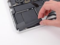
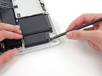
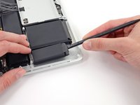
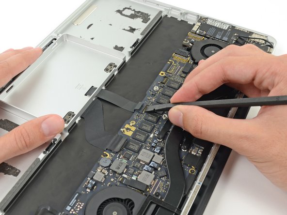
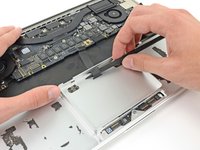
Use the flat end of a spudger to flip up the retaining flap on the trackpad ribbon cable ZIF socket.
-
-
-
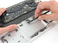
Grasp the plastic pull tab and pull the trackpad ribbon cable out of its socket.
-
-
-
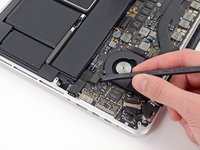
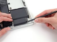
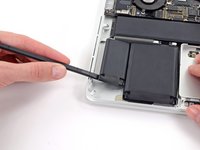
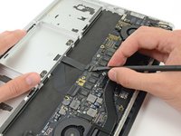
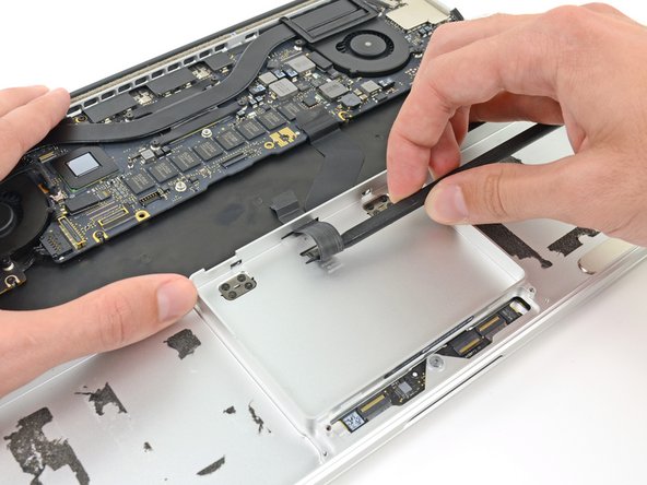
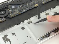
Wedge the spudger between the trackpad ribbon cable and the upper case.
-
Run the spudger along the bottom to release the trackpad ribbon cable from the adhesive securing it to the upper case.
-
-
-
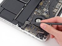
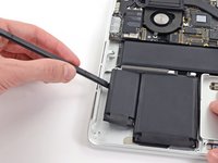
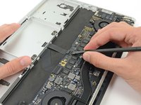
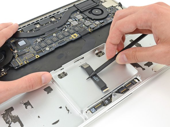
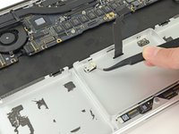
Insert the tip of a spudger in between the trackpad ribbon cable and the upper case inside the SSD assembly cavity to remove the last of the adhesive.
-
-
-
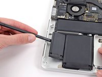
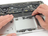
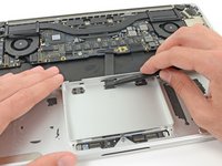
Using the tip of the spudger carefully thread the trackpad ribbon cable out of the notch near the top of the SSD assembly cavity.
-
-
-
Remove the following screws securing the trackpad brackets to the trackpad and upper case:
-
Four 1.9 mm Phillips #000 screws
-
Four 1.4 mm Phillips #000 screws
-
-
Tool used on this step:Tweezers$4.99
-
Use tweezers to remove the two trackpad mounting brackets from the upper case.
-
-
-
Guide the trackpad ribbon cable through the slot cut in the upper case. This will push the trackpad up out of its recess in the top of the upper case. Guide the trackpad out with your other hand, so it doesn't fall.
-
-
-
Gently pull the trackpad from the upper case, being careful not to snag the ribbon cable.
-


To reassemble your device, follow these instructions in reverse order.
Cancel: I did not complete this guide.
30 other people completed this guide.


8 Guide Comments
This can be done without removing the battery. The touchpad ribbon cable can be disconnected on the logic board, then snaked (gently!!) back out its channel with the battery in place.
It won't thread back through when replacing the touchpad though - it's not stiff enough. Instead, cut a strip of material from a manila folder and thread that through the channel under the battery. Then use masking tape to attach the touchpad cable to the manila strip and pull the strip out towards the logic board. The touchpad ribbon threads through the channel and the masking tape can be removed once it's in place.
Only the battery connector, SSD cable, and SSD carrier need removed.
Steps 24-34 are UNNECESSARY for this repair! Removing the adhesive portion of the battery is not required to remove the trackpad. Just lift up the top part of the battery that is screwed in and unplug the trackpad cable.