Free Shipping on Domestic Orders $75+

Logitech RS50 Base Slip Ring Installation

Prerequisite Only
This is a prerequisite-only guide! This guide is part of another procedure and isn’t meant to be used alone.

What you need

    1. Logitech RS50 Base Slip Ring Installation, Disassembly complete: step 1, image 1 of 1
      • Congratulations on completing disassembly! The remaining steps will show how to reassemble your device.

      Ask FixBot

      Add Comment

    2. Logitech RS50 Base Slip Ring Installation, Install the slip ring adhesive: step 2, image 1 of 1
      • Peel the opaque yellow liner from the slip ring adhesive strip.

      Ask FixBot

      Add Comment

    3. Logitech RS50 Base Slip Ring Installation: step 3, image 1 of 2 Logitech RS50 Base Slip Ring Installation: step 3, image 2 of 2
      • Press the exposed adhesive onto the side of the replacement slip ring and wrap it around the body.

      Ask FixBot

      Add Comment

    4. Logitech RS50 Base Slip Ring Installation: step 4, image 1 of 2 Logitech RS50 Base Slip Ring Installation: step 4, image 2 of 2
      • Use your fingers to squeeze the adhesive for ten seconds to help adhere it to the slip ring.

      • Peel away the outer liner to expose the adhesive.

      Ask FixBot

      Add Comment

    5. Logitech RS50 Base Slip Ring Installation, Install the slip ring into the adapter: step 5, image 1 of 3 Logitech RS50 Base Slip Ring Installation, Install the slip ring into the adapter: step 5, image 2 of 3 Logitech RS50 Base Slip Ring Installation, Install the slip ring into the adapter: step 5, image 3 of 3
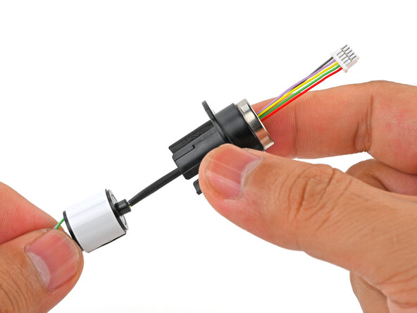
      • Thread the slip ring's short cable through the back of the slip ring adapter (the end with the arms).

      • Push the slip ring into the adapter until it's fully seated with no room to move.

      Ask FixBot

      Add Comment

    6. Logitech RS50 Base Slip Ring Installation: step 6, image 1 of 1
      • Use your fingers to squeeze the adapter arms against the slip ring for 10 seconds to adhere it in place.

      Ask FixBot

      Add Comment

    7. Logitech RS50 Base Slip Ring Installation, Install the slip ring adapter: step 7, image 1 of 1
      • Insert the slip ring's long cable into the back of the shaft and guide it through to the front.

      Ask FixBot

      Add Comment

    8. Logitech RS50 Base Slip Ring Installation: step 8, image 1 of 3 Logitech RS50 Base Slip Ring Installation: step 8, image 2 of 3 Logitech RS50 Base Slip Ring Installation: step 8, image 3 of 3
      • Align the slip ring adapter to the base using the alignment pin and slide the adapter into the shaft.

      • Make sure the pin isn't aligning with a screw hole, or the adapter won't sit flush.

      • When it's properly aligned, the adapter should sit flush against the base, and the three screw holes will be visible.

      Ask FixBot

      Add Comment

    9. Logitech RS50 Base Slip Ring Installation: step 9, image 1 of 2 Logitech RS50 Base Slip Ring Installation: step 9, image 2 of 2
      • Use a 1.5 mm hex driver to install the three 7 mm‑long slip ring adapter screws.

      • If you have trouble reaching the screws, rotate the base to get better access.

      Ask FixBot

      Add Comment

    10. Logitech RS50 Base Slip Ring Installation, Install the circuit board: step 10, image 1 of 3 Logitech RS50 Base Slip Ring Installation, Install the circuit board: step 10, image 2 of 3 Logitech RS50 Base Slip Ring Installation, Install the circuit board: step 10, image 3 of 3
      Ask FixBot

      Add Comment

    11. Logitech RS50 Base Slip Ring Installation: step 11, image 1 of 2 Logitech RS50 Base Slip Ring Installation: step 11, image 2 of 2
      • Move the cable tie into position over its circuit board screw hole.

      Ask FixBot

      Add Comment

    12. Logitech RS50 Base Slip Ring Installation: step 12, image 1 of 1
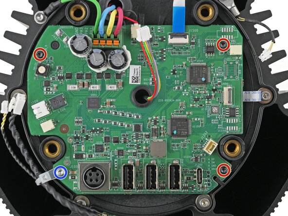
      • Use a Torx T8 driver to install the four circuit board screws:

      • Three 7.6 mm‑long screws

      • One 12 mm‑long silver screw

      Ask FixBot

      Add Comment

    13. Logitech RS50 Base Slip Ring Installation, Connect the circuit board: step 13, image 1 of 3 Logitech RS50 Base Slip Ring Installation, Connect the circuit board: step 13, image 2 of 3 Logitech RS50 Base Slip Ring Installation, Connect the circuit board: step 13, image 3 of 3
      • Use your fingers to slide the ballast temperature connector fully into its socket to connect it.

      • Repeat for the ballast connector above it.

      Ask FixBot

      Add Comment

    14. Logitech RS50 Base Slip Ring Installation: step 14, image 1 of 2 Logitech RS50 Base Slip Ring Installation: step 14, image 2 of 2
      • Insert the slip ring connector into its socket to connect it.

      Ask FixBot

      Add Comment

    15. Logitech RS50 Base Slip Ring Installation: step 15, image 1 of 2 Logitech RS50 Base Slip Ring Installation: step 15, image 2 of 2
      • Insert the base temperature connector into its socket to connect it.

      Ask FixBot

      Add Comment

    16. Logitech RS50 Base Slip Ring Installation: step 16, image 1 of 2 Logitech RS50 Base Slip Ring Installation: step 16, image 2 of 2
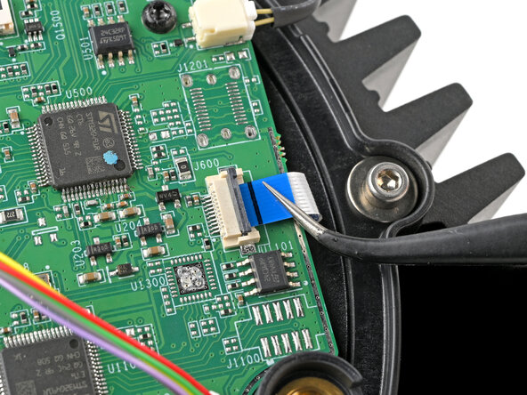
      • Slide the encoder cable fully into its ZIF socket.

      Ask FixBot

      Add Comment

    17. Logitech RS50 Base Slip Ring Installation: step 17, image 1 of 2 Logitech RS50 Base Slip Ring Installation: step 17, image 2 of 2
      • While holding the cable in place, use your finger to flip down the locking flap to secure the encoder cable.

      Ask FixBot

      Add Comment

    18. Logitech RS50 Base Slip Ring Installation, Install the back cover: step 18, image 1 of 2 Logitech RS50 Base Slip Ring Installation, Install the back cover: step 18, image 2 of 2
      • Place the back cover over the back of the base.

      Ask FixBot

      Add Comment

    19. Logitech RS50 Base Slip Ring Installation: step 19, image 1 of 1
      • Use a 5 mm hex driver to install the four 28 mm‑long back cover bolts.

      Ask FixBot

      Add Comment

    20. Logitech RS50 Base Slip Ring Installation, Install the spring: step 20, image 1 of 1
      • Insert the spring into the front of the shaft.

      Ask FixBot

      Add Comment

    21. Logitech RS50 Base Slip Ring Installation, Install the QR adapter: step 21, image 1 of 2 Logitech RS50 Base Slip Ring Installation, Install the QR adapter: step 21, image 2 of 2
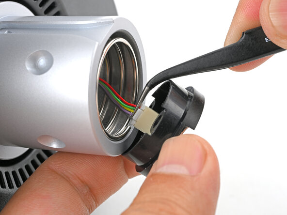
      • Use tweezers to hold the slip ring connector near the base and connect it to the QR adapter socket.

      Ask FixBot

      Add Comment

    22. Logitech RS50 Base Slip Ring Installation: step 22, image 1 of 1
      • Insert the QR adapter into the front of the shaft.

      Ask FixBot

      Add Comment

    23. Logitech RS50 Base Slip Ring Installation: step 23, image 1 of 1
      • Use a 2.5 mm hex driver to install the two 23 mm‑long QR adapter screws.

      • Even though it looks symmetrical, the QR adapter screw holes align to the shaft in only one way. If the screws don't seem to align, try rotating the adapter.

      Ask FixBot

      Add Comment

Conclusion

To reassemble your device, follow these instructions in reverse order.

Cancel: I did not complete this guide.

Arthur Shi

Member since: 01/03/18

350,781 Reputation

938 Guides authored

0 Guide Comments

Add Comment

View Statistics:

Past 24 Hours: 0

Past 7 Days: 1

Past 30 Days: 3

All Time: 50