Introduction
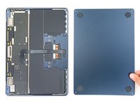
Use this guide to replace the logic board in your MacBook Air 13" 2022.
To maintain Touch ID functionality, you must also replace your Touch ID sensor with a new one that's paired to the replacement logic board. If your new logic board doesn't come with a paired Touch ID sensor, you'll lose functionality. The MacBook Air's original Touch ID sensor is uniquely paired to the logic board at the factory—and without Apple’s proprietary calibration process, even a genuine replacement Touch ID sensor from another MacBook Air won’t work.
Note: This laptop uses a combination of standard Torx and Torx Plus (IP) screws. In the case that you don't have all the necessary Torx Plus drivers, you can use standard Torx drivers instead. If you do, make sure to use constant, downward force to avoid stripping.
What you need
-
-
Power off your MacBook Air and unplug all cables.
-
Close the display and flip the laptop upside down. Keep the lid closed until you've physically disconnected the battery.
 Ask FixBot
-
-
Tool used on this step:FixMat$36.95
-
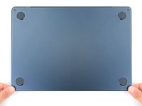
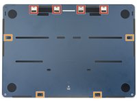
Use a P5 Pentalobe driver to remove the four 6.4 mm screws securing the lower case:
-
Two screws with a short threaded portion near the hinges
-
Two screws with a long threaded portion near the front of the MacBook
-
-
-
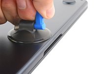
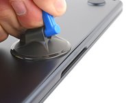
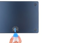
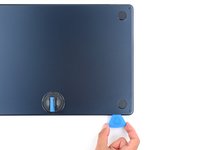
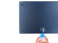
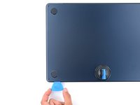
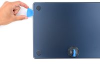
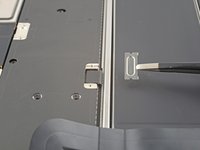
Apply a suction handle to the center of the lower case's front edge.
-
Pull up on the suction handle with strong, steady force to create a small gap between the lower case and the frame.
-
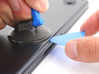
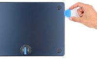
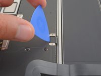
Insert an opening pick into the gap.
-
-
-
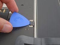
Slide the pick to the bottom right corner to release the first clip.
-
Slide the pick around the corner and up the right edge to release the next clip.
-
-
-
Insert the opening pick in the original gap created with the suction handle.
-
Slide the opening pick to the bottom left corner and up the left edge to release the two remaining snapping clips.
-
-
-
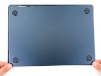
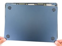
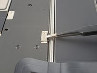
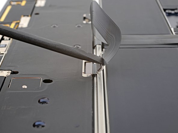
Keep the lower case flat and firmly pull it straight away from the back edge, one corner at a time, to disengage the sliding tabs.
-
-
-
Remove the lower case.
-
Set the lower case in place and align the sliding tabs with the screw heads they slide over. Press down and slide the lower case toward the back edge to engage the tabs—it'll stop sliding as the tabs engage.
-
Once the lower case is flush with the frame, press down firmly along the perimeter to engage the four snapping clips.
-
-
-
Use a T3 Torx driver to remove the two 1.5 mm screws securing the battery connector cover.
-
-
-
Use an opening pick to pry up and disconnect the battery press connector.
-
-
-
-
Use a T3 Torx driver to remove the two 1.5 mm screws securing the trackpad cable cover.
-
-
-
Use a spudger or your fingers to move the trackpad cable cover out of the way so you can access the press connector underneath.
-
-
-
Use the pointed end of a spudger to pry up and disconnect the trackpad cable press connector.
-
-
-
Peel up and remove the foam pad from the lower display cable cover to reveal a hidden screw.
-
-
-
Use a T3 Torx driver to remove the fourteen 1.5 mm screws securing the various cable covers.
-
-
Tool used on this step:Tweezers$4.99
-
Use tweezers or your fingers to remove the six cable covers.
-
-
-
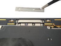
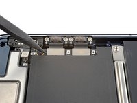
Remove the four screws securing the upper display cable cover:
-
Two 2.5 mm P2 Pentalobe screws
-
Two 2.5 mm 3IP Torx Plus screws
-
-
-
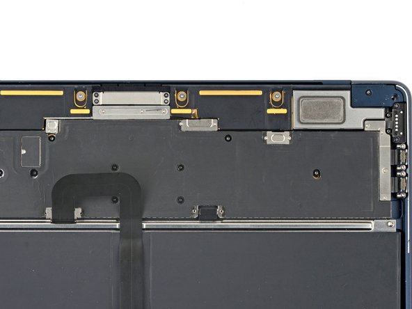
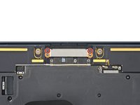
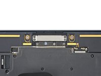
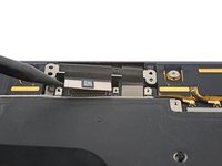
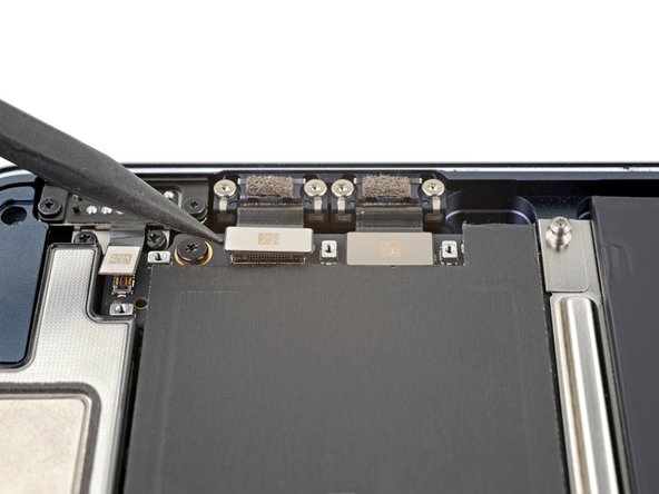
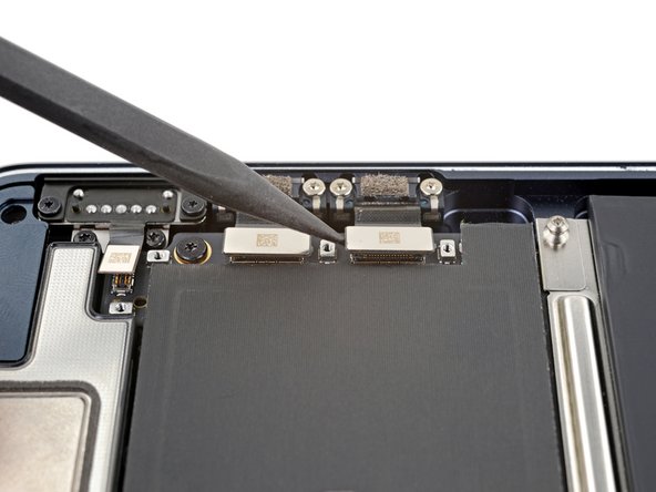
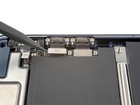
Use the pointed end of a spudger to pry up and disconnect both display cable press connectors.
-
-
-
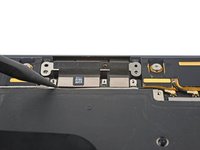
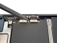
Disconnect the microphone array press connector, directly to the left of the display cable.
-
-
-
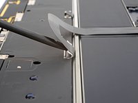
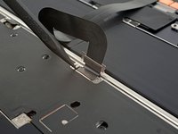
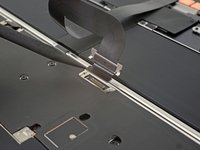
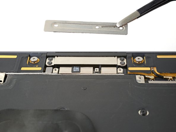
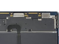
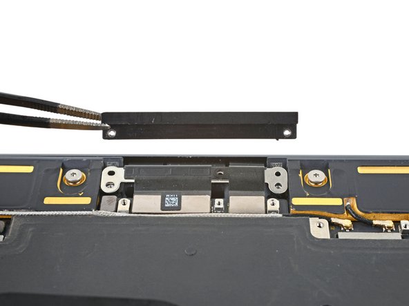
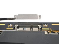
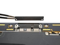
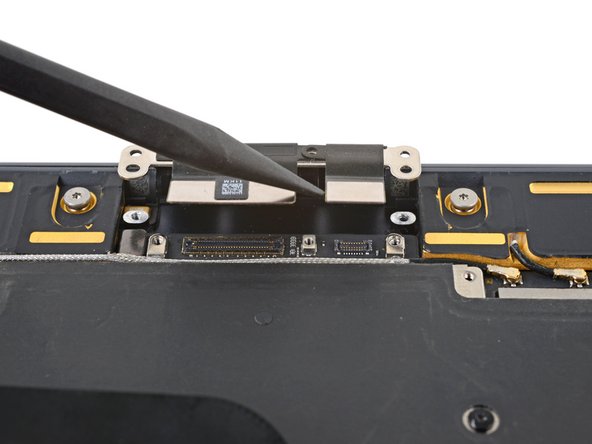
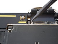
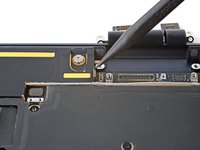
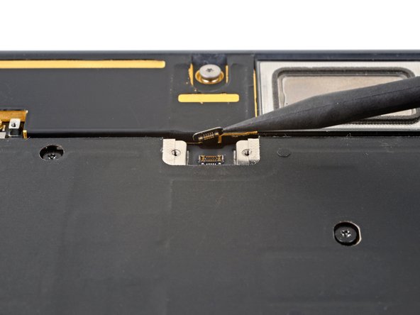
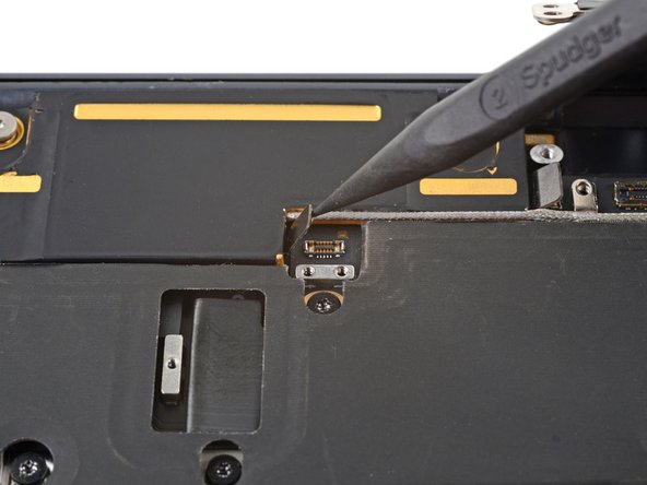
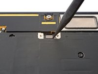
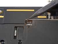
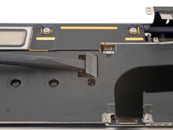
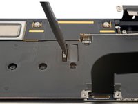
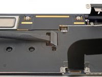
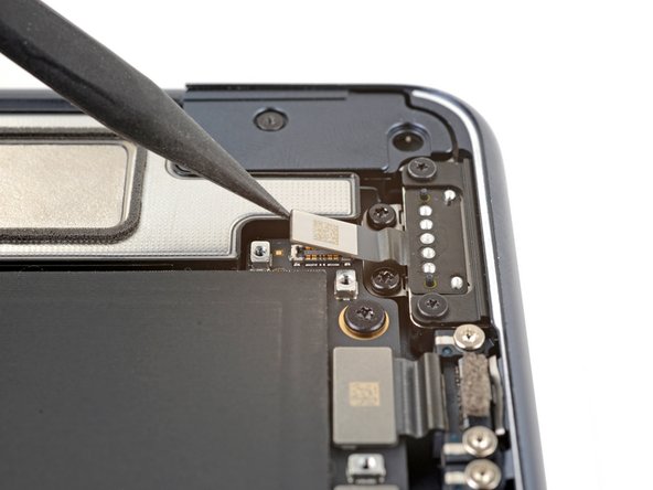
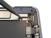
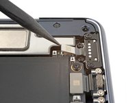
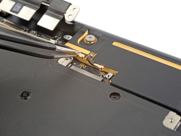
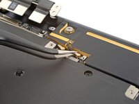
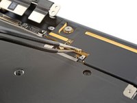
Insert the flat end of a spudger between the the interconnect cable and the screw post.
-
Pry up and disconnect the interconnect cable.
-
-
-
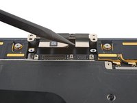
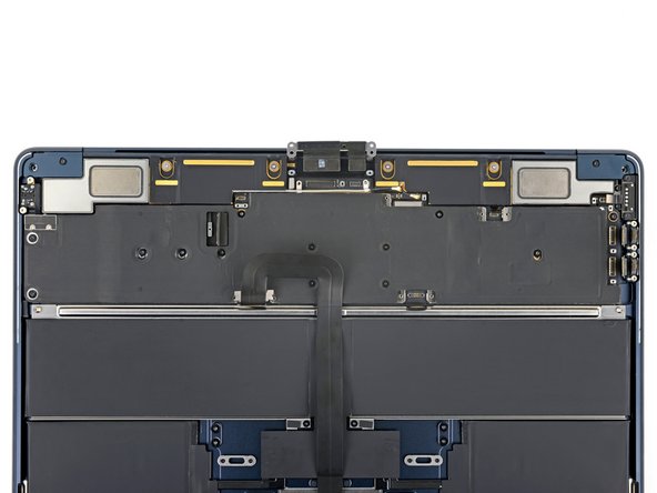
Use a pair of tweezers to grip the first antenna connector, as close to its base as possible.
-
Lift straight up to disconnect the cable.
-
Repeat for the second antenna cable.
-
-
-
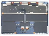
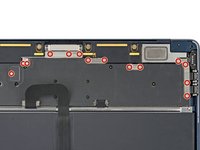
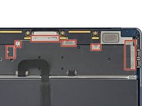
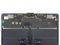
Remove the nine screws securing the logic board:
-
Three 3.8 mm T5 Torx screws
-
One 3.6 mm T5 Torx screw
-
Two 3.4 mm T5 Torx screws
-
One 3.1 mm T5 Torx screw
-
Two 2.7 mm 3IP Torx Plus screws
-
-
-
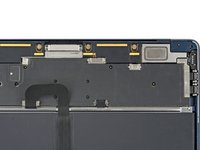
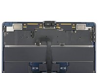
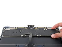
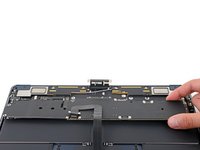
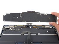
Grip the right side of the logic board and slide it towards the trackpad until it clears the overhangs near the speakers.
-
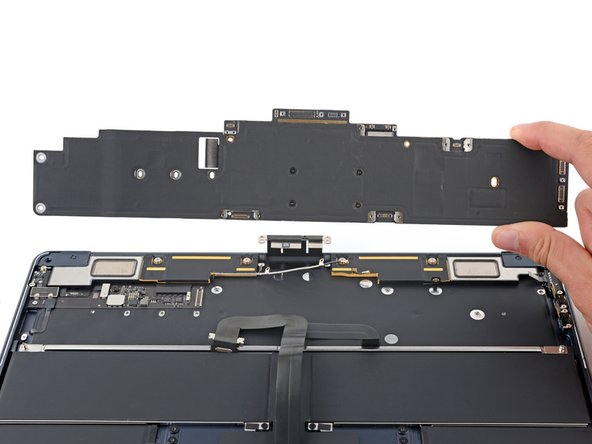
Remove the logic board.
-
-
-
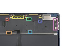
Right speaker cable
-
Trackpad cable
-
Display cables and microphone array cable
-
Antenna cables
-
Battery cable
-
Left speaker cable
-
USB-C and MagSafe cables
-


Compare your new replacement part to the original part—you may need to transfer remaining components or remove adhesive backings from the new part before you install it.
To reassemble your device, follow these instructions in reverse order.
Take your e-waste to an R2 or e-Stewards certified recycler.
Repair didn’t go as planned? Try some basic troubleshooting or check out our Answers community for help.
Cancel: I did not complete this guide.
10 other people completed this guide.


3 Guide Comments
Hi,
Is it normal that after replacing logic board and Touch ID, apple diagnostic comes up with 2 errors ndk001 als001.
One of which is ambient light sensor and the other is keyboard.
Upon testing all the keys on the keyboard all keys are working including Touch ID.
And by shining a flashlight in the light sensor the screen does get brighter.
So it looks like none of the error code is correct that apple diagnostic shows.
Is this a known thing or does this only happen to me?
Peter
My 2022 Macbook Air died at 34 months. Looking back, the MBA that I had before this one lasted just a little longer before it died (39 months). So, when this one died, I bought a new 15" MBA. I decided to take a look inside the 2022 MBA and destroy the SSD before I sent it to be recycled. Found these instructions and saw the replacement parts did not mention an SSD, just a logic board. So, I assumed that all components (CPU, RAM, SSD, etc.) were on one 'part'. Followed these instructions and discovered that this is true. In any case, at age 65 with failing eyesight and trembling hands, I was able to disassemble the MBA. But I could NOT reassemble it. Trying to reattach the connectors or even get the screws back in the right places was impossible for me. Probably very challenging for a young, steady-handed newbie. Lesson learned: disposable, not repairable. These do not last, fail at about 36 months and cannot be easily fixed. So, I am 'subscribing' to the Apple MBA program at about $600/year (1800/3 years).