Introduction
Follow this guide to install a Framework Desktop Mainboard into a Mini-ITX case.
The Framework Desktop Mainboard is compatible with a standard Mini-ITX case, ATX Power Supply, and 120mm CPU Fan. For detailed parts compatibility, click here.
For information on the Front Panel IO Connectors, click here.
This guide only shows installing the Mainboard and assumes that a power supply and antenna module are already installed.
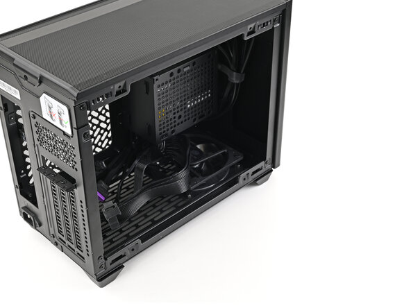
This guide features a Cooler Master NR200 case, but the procedure is identical across most Mini-ITX cases.
What you need
-
-
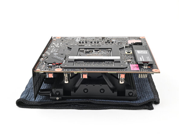
Place the Mainboard on your work surface with its heatsink resting on a soft, clean cloth.
-
-
-
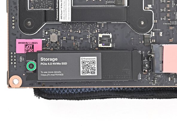
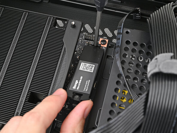
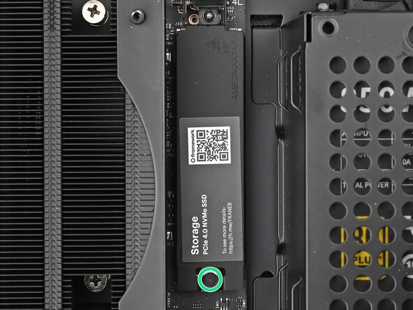
Use your Framework Desktop Screwdriver to loosen the captive T5 Torx screw securing the secondary storage.
-
-
-
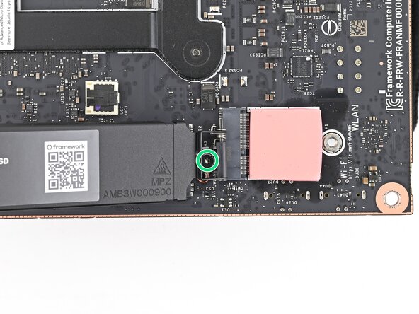
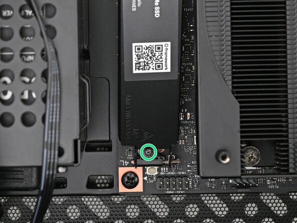
While securing the secondary storage heat spreader with one hand, use your Framework Desktop Screwdriver to remove the 4.5 mm‑long T5 Torx screw securing it.
-
-
-
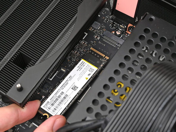
Lift the secondary storage heat spreader out of the Desktop and remove it.
-
Follow the guide normally, making sure to ignore instructions that involve the secondary heat spreader.
-
-
-
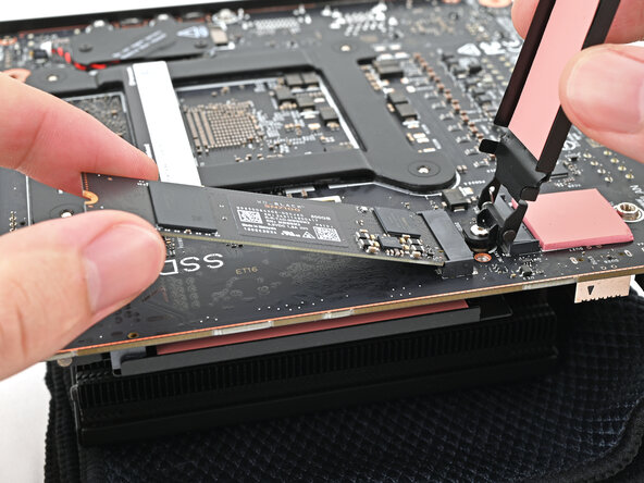
While holding the heat spreader upright, align the SSD's gold contacts with its socket.
-
Insert the SSD into the socket at a shallow angle. The gold contacts should be mostly covered by the socket.
-
-
-
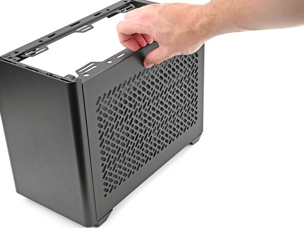
Remove the side panel from your case so you can access the cutout for the Mainboard.
-
-
-
Grip the Mainboard by the heatsink and place it into its cutout, making sure the ports aligns with its slot in the case.
-
-
-
Use your Framework Desktop Screwdriver to install the four 8.2 mm‑long Phillips screws securing the Mainboard.
-
-
-
Use your Framework Desktop Screwdriver to loosen the captive T5 Torx screw securing the primary storage.
-
-
-
-
While securing the primary storage heat spreader with one hand, use your Framework Desktop Screwdriver to remove the 4.5 mm‑long T5 Torx screw securing it.
-
-
-
Lift the primary storage heat spreader out of the desktop and remove it.
-
Follow the guide normally, making sure to ignore instructions that involve the primary storage heat spreader.
-
-
-
While holding the heat spreader upright, align the SSD's gold contacts with its socket.
-
Insert the SSD into the socket at a shallow angle. The gold contacts should mostly be covered by the socket.
-
Lay the heat spreader back onto the SSD.
-
-
-
Orient the fan so its label is facing downward and the cable(s) are pointing towards their sockets on the Mainboard.
-
Lay the fan on top of the heatsink.
-
Lay the fan duct on top of the fan with the lip facing upward.
-
Align the screw holes on the fan duct with the ones on the fan.
-
-
-
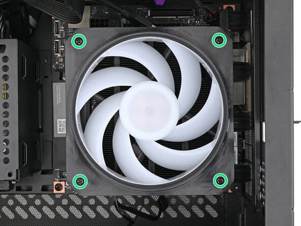
Use your Framework Desktop Screwdriver to install the four 27.3 mm‑long Phillips screws securing the CPU fan and fan duct.
-
-
-
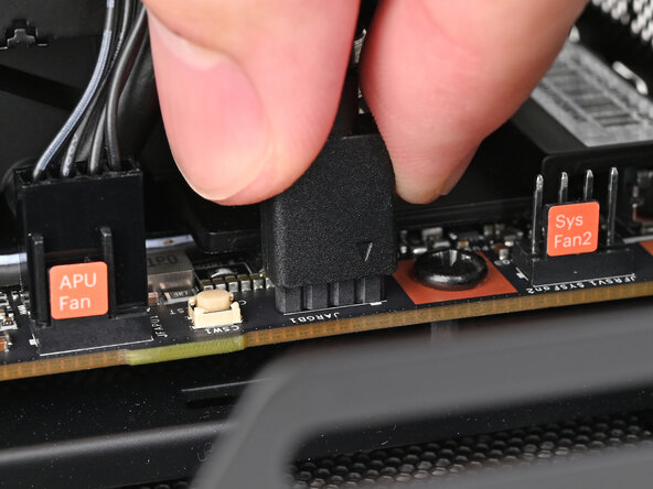
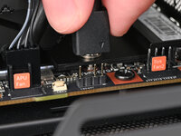
Slide the main fan cable over the four-pronged connector labeled "APU Fan," making sure the orange label slots between the vertical lines.
-
-
-
Use your fingers to slide the RGB cable over the three pronged connector located to the right of the "APU Fan" connector.
-
-
-
Slide the cable over the four-pronged connector labeled "Sys Fan1," making sure the orange label slots between the vertical lines.
-
-
-
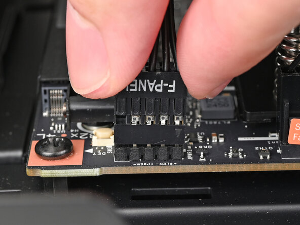
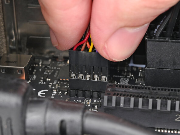
Slide the front panel header cable into its 9-pin connector underneath the primary storage.
-
-
-
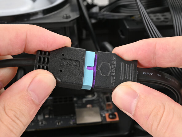
Slide the USB port cable into one of the USB Type-E 20-pin sockets above the primary storage.
-
-
-
Orient the 8-pin CPU power supply cable so its clip(s) are facing the heatsink.
-
Slide the cable into its socket on the Mainboard until you feel its clips click into place.
-
-
-
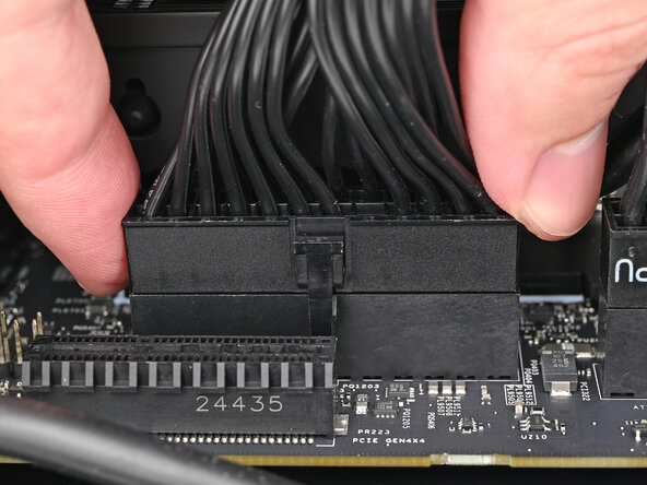
Orient the 24-pin main power supply cable so its clip is facing away from the heatsink.
-
Slide the cable into its socket on the Mainboard until you feel its clip click into place.
-
-
-
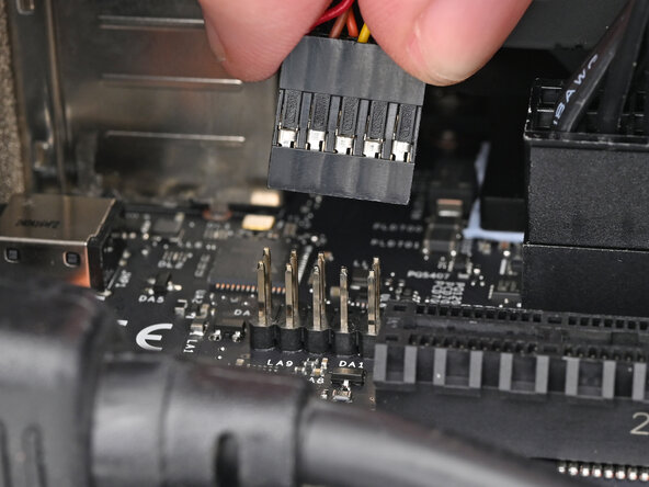
Slide the HD audio cable into its 9-pin connector next to the main power supply connector.
-
-
-
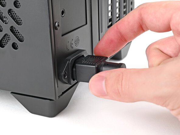
Disassemble your case enough to access the bottom side of the Mainboard.
-
-
-
Lay your case down so the bottom of the Mainboard is facing upright.
-
-
-
Align the Wi-Fi module's gold contacts and notch with the socket on the Mainboard.
-
Insert the Wi-Fi module into the socket at a shallow angle. The gold contacts should mostly be covered by the socket.
-
-
-
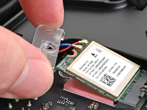
Hold the Wi-Fi module down with your fingers.
-
Position the antenna cable connector over the left Wi-Fi module's coaxial socket.
-
Use your finger to press the connector into place. You should feel a faint click, and the cable will stay attached to the socket by itself.
-
Repeat the procedure with the other antenna cable.
-
-
-
Use your Framework Desktop Screwdriver to install the 7.0 mm‑long screw securing the Wi-Fi module.
-
-
-
You're done installing your Framework Desktop Mainboard! If you haven't transferred your data, you'll need to install an OS.
-


For drivers, firmware, and software updates, check out this page.
If you need help, contact Framework support.
