Introduction
Use this guide to upgrade your Framework Laptop 13 to the Framework Laptop 13 Pro Bottom Cover, Battery, Speakers, Audio Board and Haptic Touchpad.
You can't mix and match the aforementioned parts from across the 13 and 13 Pro lineup. Each part within the Bottom Cover (minus the Mainboard) needs to be replaced. For detailed parts compatibility, click here.
What you need
-
-
-
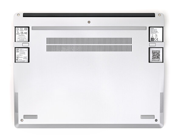
Unplug all cables and fully shut down your laptop from the OS.
 Ask FixBot
-
-
-
-
-
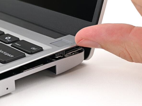
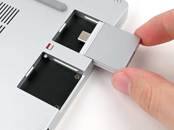
While pressing down the release button, grip the lip of the Expansion Card and pull it out of its slot to release it.
-
-
-
Slide the Expansion Card out of its slot and remove it.
-
Remove the remaining Expansion Cards.
-
-
-
-
-
Use your Framework Screwdriver to loosen the five captive T5 Torx screws securing the Input Cover.
-
-
-
Flip over the laptop and open it.
-
Use your fingers to lift the Input Cover up and release it from its magnets.
-
-
-
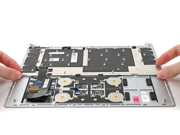
Flip the top of the Input Cover so the Keyboard is facing down.
-
Rest the Input Cover over the Battery, making sure the Touchpad Cable isn't being strained.
-
-
-
Insert your finger into the Touchpad Cable press connector loop.
-
Lift up to disconnect the Touchpad Cable from the Mainboard.
-
-
-
-
-
Use your fingers to grip the edges of the Battery connector and slide it straight out of its socket to disconnect the Battery.
-
-
-
-
-
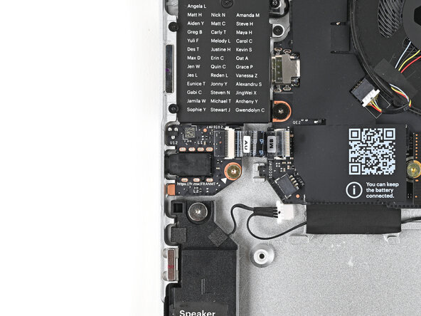
Use your fingers to grip the edges of the Speaker cable connector.
-
Pull the connector straight out of its socket to disconnect it.
-
-
-
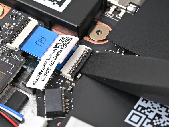
Use the flat end of your Framework Screwdriver, or a clean fingernail, to lift up the locking tab on the Audio Board ZIF connector on the Mainboard.
-
-
-
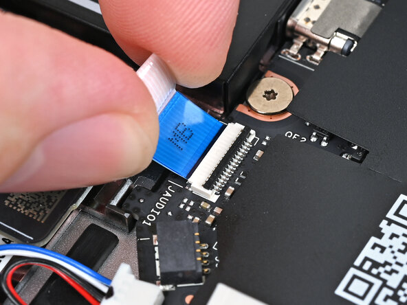
Use your fingers to lightly grip the Audio Board cable and slide it straight out of its socket.
-
-
-
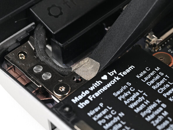
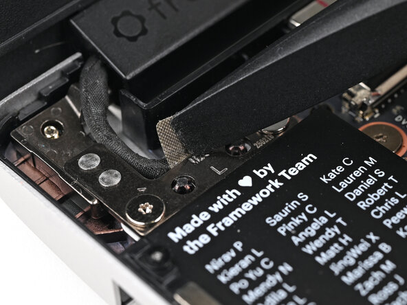
Use the flat end of your Framework Screwdriver to peel off the grounding tape on the left Hinge.
-
-
-
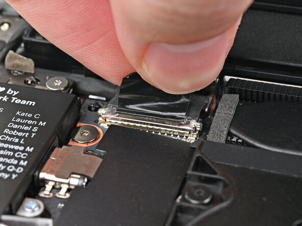
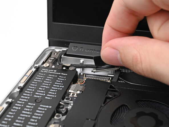
Grip the Display eDP Cable connector by its pull tab and lift up to disconnect it.
-
-
-
Lift the Display eDP Cable out of its slot in the Bottom Cover.
-
-
-
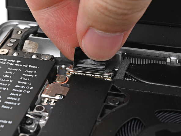
Grip the Webcam Cable connector by its pull tab and lift up to disconnect it.
-
-
-
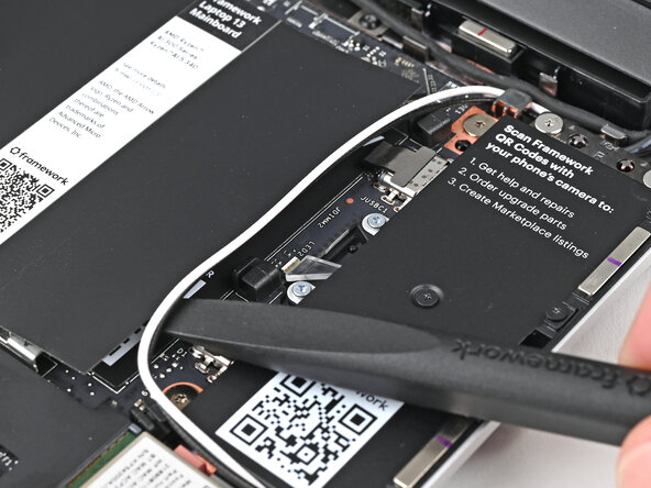
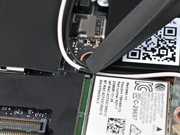
Use your fingers or the flat end of the Framework Screwdriver to lift the two Antenna Cables out of their clips on the Mainboard.
-
-
-
Use your Framework Screwdriver to loosen the captive T5 Torx screw securing the Wi-Fi module.
-
-
-
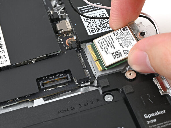
Grip the end of the Wi-Fi module with the screw hole and slide it out of its socket.
-
Position the Wi-Fi module to the right of the laptop to keep it out of the way of the Mainboard.
-
-
-
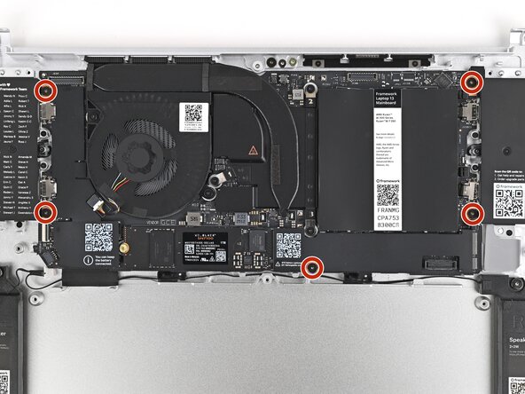
Use your Framework Screwdriver to remove the five 1.5 mm‑long T5 Torx screws securing the Mainboard.
-
-
-
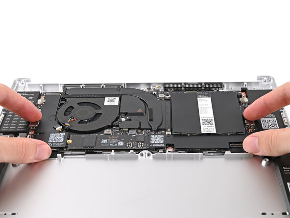
Use your fingers to lift the bottom edge of the Mainboard enough to grip its edges.
-
Lift the Mainboard off its alignment pegs and remove it.
-
-
-
-
-
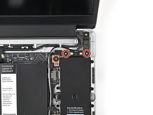
While supporting the Top Cover with one hand, use your Framework Screwdriver to remove two 4.0 mm‑long T5 Torx screws on each Hinge connected to the Bottom Cover (four total).
-
-
-
Lift the Top Cover off its two sets of alignment pegs on the Bottom Cover and remove it.
-
-
-
-
-
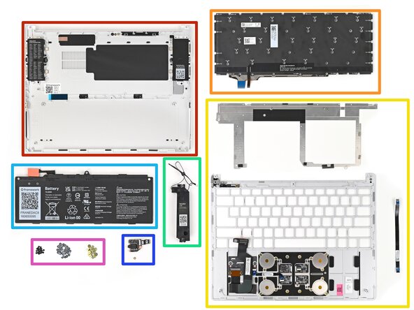
Bottom Cover Kit
-
Keyboard
-
Input Cover Frame (including the Keyboard Bracket and Fingerprint Reader Cable)
-
Speaker Kit
-
Battery
-
Audio Board Kit
-
Fastener Kit – Input Cover and Keyboard (only the Keyboard and Keyboard Bracket screws are needed—the rest can be kept as spares)
-
-
-
Separate the Speakers from each other if they're attached.
-
-
-
-
Place the left Speaker into its slot on the Bottom Cover, making sure it's aligned with its screw posts and threaded through its alignment peg.
-
-
-
Use your Framework Screwdriver to tighten the two T5 Torx screws on each Speaker (4 total).
-
-
-
Starting from the right Speaker, press the speaker cable into its metal and plastic clips on the Bottom Cover.
-
-
-
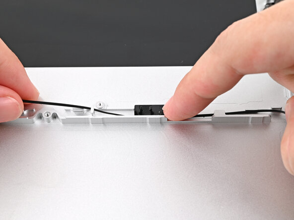
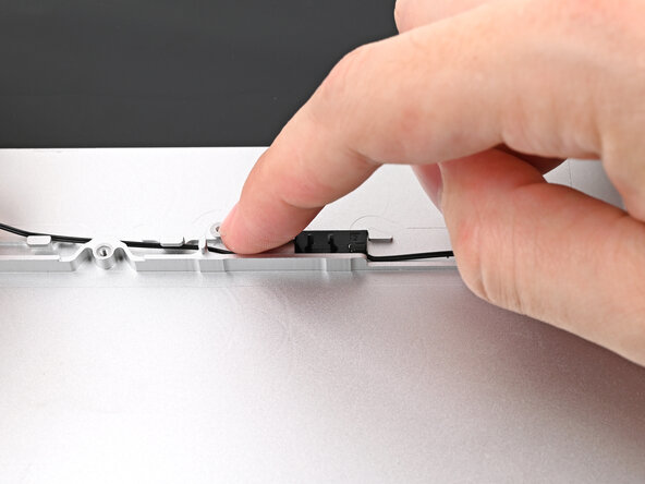
If you're having difficulty pressing the speaker cable into its plastic clips, twist the cable so it's vertical and use the flat end of your Framework Screwdriver to press it down.
-
-
-
Repeat the previous two steps for the section of Speaker Cable near the left Speaker.
-
-
-
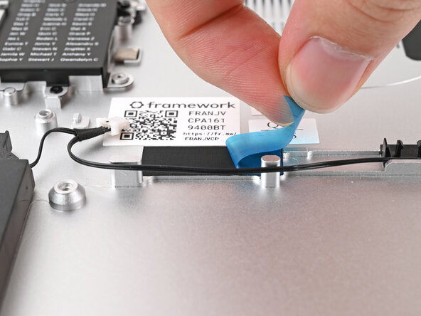
Remove the blue liner from the black tape near the left Speaker.
-
-
-
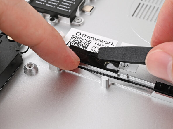
Slide the flat end of your Framework Screwdriver under the black tape and separate one of its long edges from the Chassis.
-
-
-
While holding the tape out of the way, lay the Speaker Cable into the channel underneath it.
-
Press the tape over the Speaker Cable to adhere it to the Chassis.
-
-
-
Before continuing, check the pins on the Battery socket and make sure they aren't bent.
-
-
-
Grab the Mainboard by its edges and place it into the Bottom Cover and onto its alignment pegs.
-
-
-
Use your Framework Screwdriver to install the five 1.5 mm‑long T5 Torx screws securing the Mainboard.
-
-
-
Angle the left edge of the Audio Board downward and slide the headphone jack through its hole in the Bottom Cover.
-
Align the screw hole in the Audio Board with its post and press it flat to the Bottom Cover.
-
-
-
Use your Framework Screwdriver to install the 3.0 mm‑long T5 Torx screw securing the Audio Board.
-
-
-
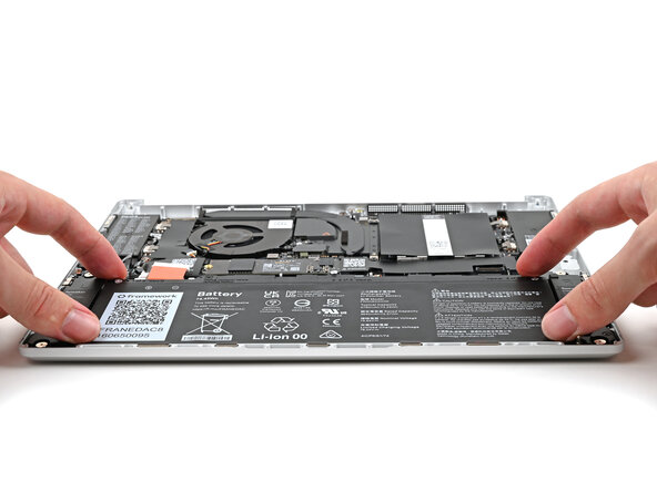
Insert the Battery into its cutout, making sure its plastic tabs are slotted into the Bottom Cover.
-
-
-
Use your Framework Screwdriver to tighten the three captive T5 Torx screws securing the Battery.
-
-
-
Place the Top Cover on its two sets of alignment pegs on the Bottom Cover.
-
Make sure all of the cables are above the Bottom Cover before continuing.
-
-
-
While supporting the Top Cover with one hand, use your Framework Screwdriver to install two 4.0 mm‑long T5 Torx screws on each Hinge connected to the Bottom Cover (four total).
-
-
-
Place the Display eDP Cable into its slot on the Bottom Cover.
-
-
-
Press the Display eDP Cable connector straight down into its socket to connect it.
-
-
-
Press the grounding tape onto the left Hinge to adhere it.
-
-
-
Slide the Audio Board cable straight into its socket.
-
-
-
Use the flat end of your Framework Screwdriver, or a clean fingernail, to press down the locking tab on the Audio Board ZIF connector.
-
-
-
Use your finger to guide the Webcam Cable into its metal pegs on the Bottom Cover.
-
-
-
Press the Webcam Cable connector straight down into its socket to connect it.
-
-
-
Use your finger to press the Antenna Cables into their metal clip on the Bottom Cover.
-
Rotate the cables around the raised corner at the top right of the Mainboard so they point towards the Wi-Fi module.
-
-
-
Use your Framework Screwdriver to loosen the captive T5 Torx screw securing the Wi-Fi module cover.
-
-
-
Align the Wi-Fi module's gold contacts and notch with the socket on the Mainboard.
-
Insert the Wi-Fi module into the socket at a shallow angle. The gold contacts should mostly be covered by the socket.
-
-
-
Hold the Wi-Fi module down with your finger.
-
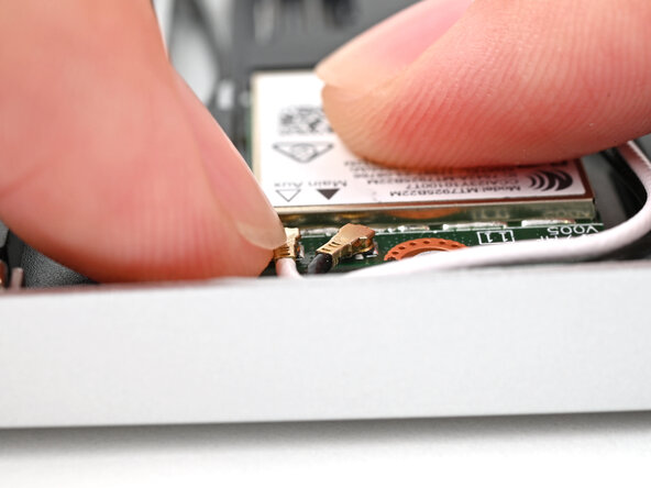
Position the black antenna cable connector over the Wi-Fi module's coaxial socket indicated by the black arrow.
-
Use your finger to press the connector into place. You should feel a faint click, and the cable will stay attached to the socket by itself.
-
Repeat the procedure with the white antenna cable.
-
-
-
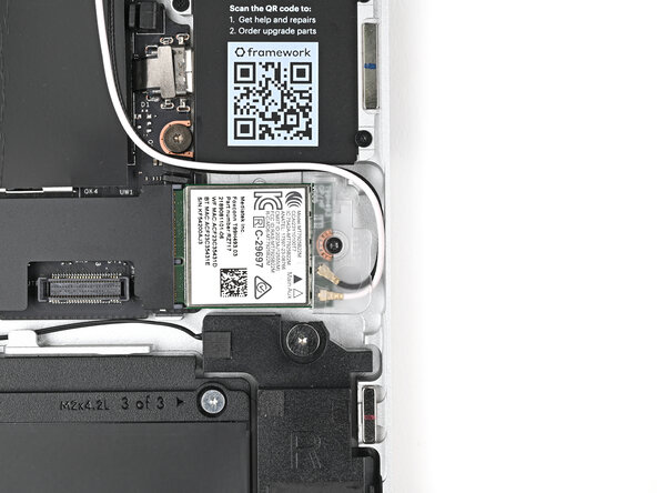
Use your Framework Screwdriver to tighten the captive T5 Torx screw securing the Wi-Fi module.
-
-
-
Use the flat end of your Framework Screwdriver to press the two Antenna Cables into their rubber clips on the Mainboard.
-
-
-
Use your fingers to align the Battery connector with its socket and slide it straight in to reconnect the Battery.
-
-
-
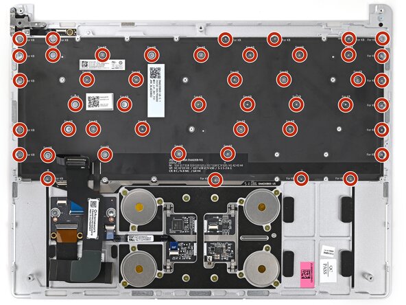
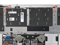
Use your Framework Screwdriver to install the forty-six 1.2 mm‑long black PH0 screws securing the Keyboard.
-
-
-
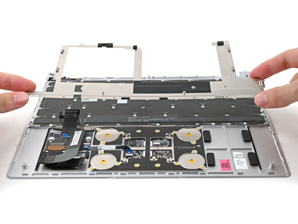
Place the Keyboard Bracket onto its alignment pegs.
-
-
-
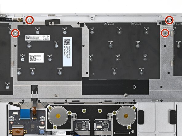
Use your Framework Screwdriver to install the twenty 1.3 mm‑long silver PH0 screws securing the Keyboard Bracket.
-
-
-
Use the flat end of your Framework Screwdriver, or a clean fingernail, to lift up the locking tab on the Fingerprint Reader ZIF connector located on the Fingerprint Reader board.
-
-
-
Slide the Fingerprint Reader Cable straight into its socket.
-
-
-
Use the flat end of your Framework Screwdriver, or a clean fingernail, to press down the locking tab on the Fingerprint Reader ZIF connector.
-
-
-
Repeat the previous three steps to connect the Fingerprint Reader Cable on the Hub Board.
-
-
-
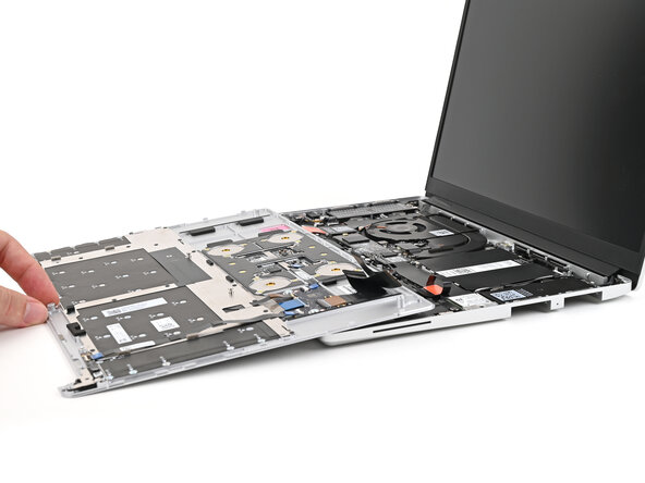
Position the Input Cover, keyboard down, on top of the laptop so it just covers the Battery.
-
-
-
Insert your finger into the Touchpad Cable press connector loop.
-
Align the press connector over its socket and press down with your finger.
-
-
-
Flip the Input Cover over the laptop and align the bottom edges.
-
-
-
Close the laptop and flip it over.
-
Use your Framework Screwdriver to tighten the five captive T5 Torx screws securing the Input Cover.
-
-
-
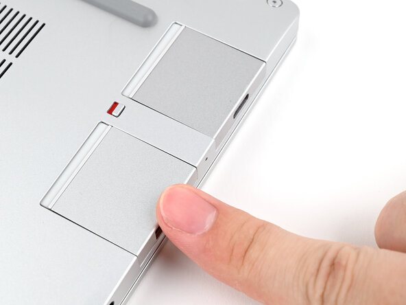
Slide an Expansion Card into an Expansion Card slot.
-
Repeat for the remaining Expansion Cards.
-
-
-
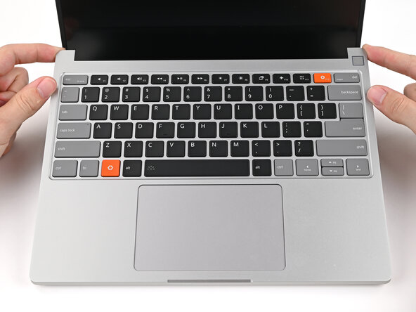
You've finished upgrading your Framework Laptop! Check out this page to update to the latest drivers, firmware, and software.
-
-
















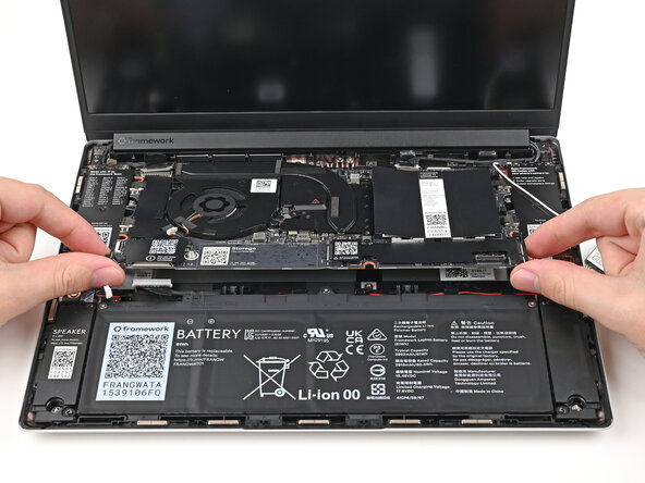
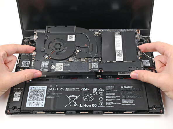



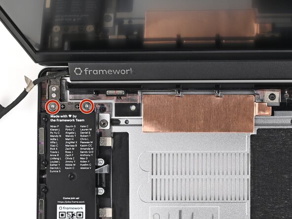












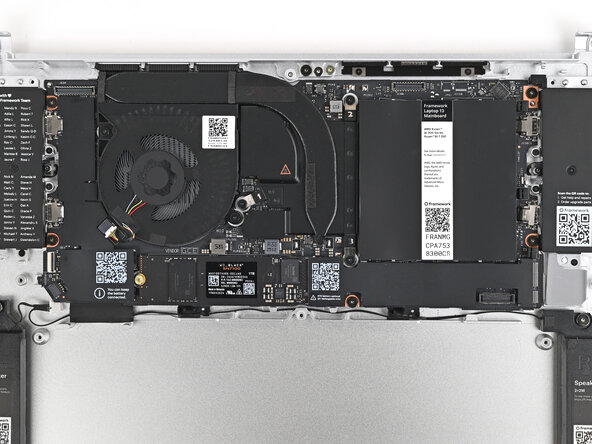

































Take your e-waste to an R2 or e-Stewards certified recycler.
If you need help, contact Framework support.

