Introduction
If your Flydigi Apex 5 controller joysticks are not properly responding to inputs, the issue may be a broken or failing joystick module.
Follow this guide to replace the left and right joysticks.
Warning: Lithium-Ion batteries can be a fire hazard. If the controller battery appears swollen, follow iFixit's guide on What to do with a swollen battery.
What you need
-
-
-
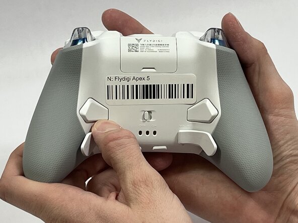
Orient the controller so that its back is facing you.
-
Apply firm downward pressure to remove both the M3 and M4 back paddles.
 Ask FixBot
-
-
-
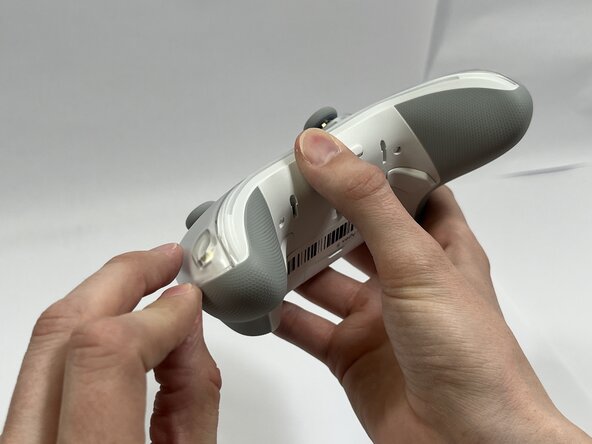
Turn the controller over so its front faces you.
-
Remove the D-pad by firmly pulling it away from the body of the controller.
-
-
-
Remove the clear, magnetically-adhered faceplate of the controller by firmly pulling it away from the body of the controller starting from the edge of the faceplate.
-
-
-
Remove the small cover from the rear of the controller by pushing it upward.
-
Remove the two 5.8mm screws behind the battery cover using a Phillips #0 screwdriver.
-
-
-
Turn the controller over so its front faces you.
-
Remove the six 10mm long screws from the front of the controller using a Torx T6 screwdriver.
-
-
-
Insert the plastic opening tool between the top and bottom plastic controller molds, then pry until the two pieces separate.
-
-
-
Carefully remove the back paddle ribbon cable with the angled tweezers or spudger.
-
-
-
-
Press a prong of each side of the angled tweezers under the lip of the power supply cable connector and pull the plastic connector out of its terminal.
-
Pull the power supply cable through the plastic cable guides.
-
-
-
-
-
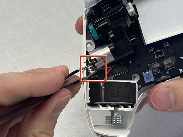
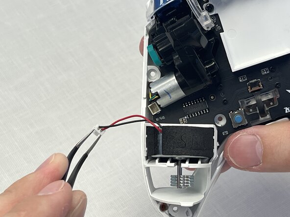
Press a prong of each side of the angled tweezers under the lip of the motor's power supply connector and pull the plastic connector out of its terminal.
-
Lift the motor directly upward out of its casing.
-
-
-
Press a prong of each side of the curved tip tweezers under the lip of the motor's power supply connector and pull the plastic connector out of its terminal.
-
Lift the motor directly upward out of its casing.
-
-
-
-
-
Remove the USB-C faceplate by inserting the spudger as shown, pushing the spudger forward while twisting slightly.
-
-
-
Remove the two 1mm screws using a Phillips #0 screwdriver.
-
Remove the plastic battery mold by lifting away from the controller.
-
-
-
Remove the four 5mm screws using a Phillips #00 screwdriver.
-
Remove the two vibration motor housings by pulling away from the controller.
-
-
-
Remove the three 1mm screws using a Phillips #1 screwdriver.
-
Use your index finger to push on the left joystick, while also pulling on the motherboard with your other hand.
-
-
-
Lift the latch that retains the right joystick flex cable.
-
Gently pull the cable away from the connector.
-
-
-
Lift the latch that retains the right joystick flex cable.
-
Gently pull the cable away from the connector.
-
-
-
Remove the three 6mm screws using a Phillips #1 screwdriver.
-
On the other side of the board, use the spudger to separate the trigger module from the blue rotation sensor.
-
-
-
After reassembling the controller with new joystick modules, you must recalibrate the joysticks. To do so, power on the controller and hold Start+Select+DPad up for 3 sec. Rotate the joysticks a few time and click them in to calibrate them and hit Start+Select+Dpad up again up to exit the calibration. Credit: @hoxigen
-
-






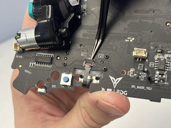


To reassemble your device, follow these instructions in reverse order.
NOTE: The flex cables have a line on the side opposing their contacts. This line indicates when the cable is properly seated in the connector. The line should be flush with or hidden by the connector.
Cancel: I did not complete this guide.
One other person completed this guide.

Team

Idaho State University, Team 1-3, Watkins Spring 2026 Member of Idaho State University, Team 1-3, Watkins Spring 2026
ISU-WATKINS-S26S1G3
4 Members
60 Guides authored
3 Guide Comments
Amazing guide! One additional thing to mention is the calibration process after swapping the joysticks. You need to power on the controller and hold Start+Select+DPad up for 3 sec. Rotate the joysticks a few time and click them in to calibrate them and hit Start+Select+Dpad up again up to exit the calibration!
@hoxigen Thank you for pointing this out! I have added it as the last step of the guide. Thanks again for the info!
Where can i find joystick modules to replace the old ones
