Introduction
Follow this guide to replace the motherboard on a Sony PlayStation 5 DualSense controller. This will fix a drifting joystick or damaged charging port.
This guide assumes that the joysticks are soldered onto the replacement motherboard. Because the joysticks are calibrated during manufacturing, replacing them or transferring them to a new motherboard will result in uncalibrated joysticks that are likely to drift.
This guide requires desoldering and soldering the vibration motor wires.
Note: This guide is for DualSense controllers with an FCC ID ending in 1. Check the back of your controller to verify your model. If yours ends in A, there will be differences in the internal design.
What you need
-
-
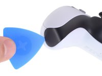
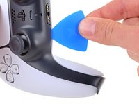
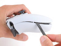
Insert an opening pick underneath the middle trim at the bottom-right corner of the controller to release the clips securing it to the case.
 Ask FixBot
-
-
-
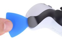
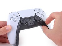
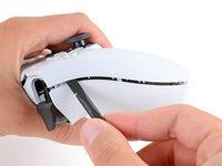
Slide the opening pick along the lower-right edge of the middle trim to release the clips securing it to the case.
-
-
-
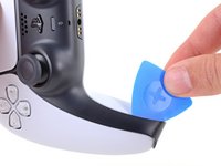
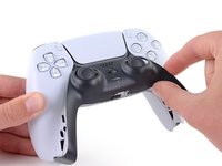
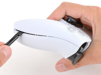
Insert an opening pick underneath the middle trim at the bottom-left corner of the controller to release the clips securing it to the case.
-
-
-
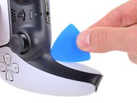
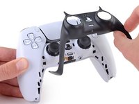
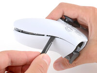
Slide the opening pick along the lower-left edge of the middle trim to release the clips securing it to the case.
-
-
-
Use your fingers to lift up the bottom edge of the middle trim to release the remaining clips.
-
Lift the middle trim over the joysticks to remove it.
-
-
-
With one hand, grip the controller and use your thumb to hold down the left trigger.
-
With your free hand, insert the flat end of a spudger between the L1 and L2 buttons.
-
Use the spudger to gently pry the L1 button away from the controller and remove it, holding your finger over the button so it doesn't eject.
-
-
-
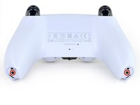
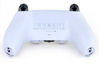
Use a Phillips screwdriver to remove the two 6.4 mm screws securing the bottom corners of the lower case.
-
-
-
Use a Phillips screwdriver to remove the two 6.4 mm screws behind the L1 and R1 buttons.
-
-
-
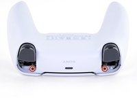
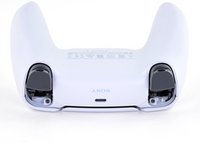
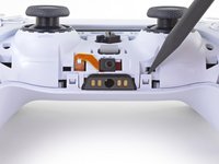
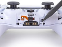
Use the point of a spudger to release the two clips on either side of the headset jack.
-
-
-
-
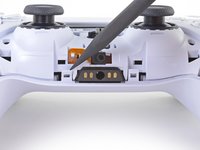
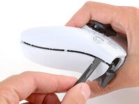
Insert the flat end of a spudger between the front and rear shells near the bottom of the left edge.
-
Slide the spudger along the left edge and gently pry the shells apart to release the clips.
-
-
-
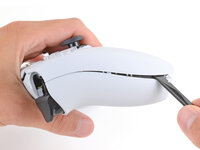
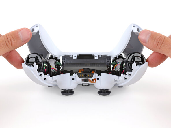
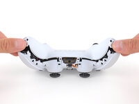
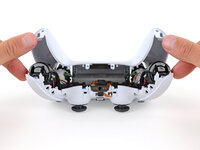
Lay your controller upside down so the joysticks are on your work surface.
-
Hold the controller down with your fingers and use your thumbs to lift the rear case away from the controller to fully separate it.
-
-
Tool used on this step:Tweezers$4.99
-
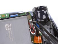
Use a pair of tweezers or your fingers to disconnect the battery from the motherboard.
-
-
Tool used on this step:Tweezers$4.99
-
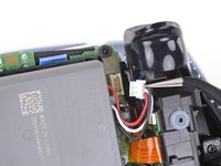
Grab the lower microphone ribbon cable pull tab with your fingers or a pair of tweezers and disconnect it from the motherboard.
-
-
-
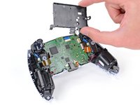
Use a Phillips screwdriver to remove the 6.4 mm screw securing the battery bracket.
-
-
-
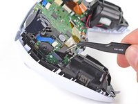
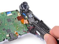
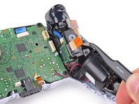
Grip the right trigger assembly ribbon cable pull tab with a pair of tweezers or your fingers and pull up to disconnect it from the motherboard.
-
-
-
Grip the right trigger assembly ribbon cable pull tab with a pair of tweezers or your fingers, and pull up to disconnect it from the trigger assembly.
-
Remove the ribbon cable.
-
-
-
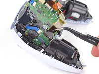
Grip the left trigger assembly ribbon cable pull tab with a pair of tweezers or your fingers and pull up to disconnect it from the motherboard.
-
-
-
Grip the left trigger assembly ribbon cable pull tab with a pair of tweezers or your fingers, and pull up to disconnect it from the trigger assembly.
-
Remove the ribbon cable.
-
-
-
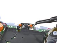
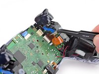
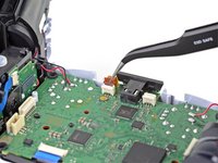
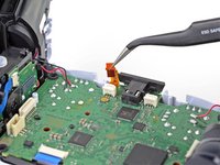
Use a pair of tweezers or your fingers to grip the upper microphone ribbon cable pull tab, and pull up to disconnect it from the motherboard.
-
-
-
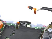
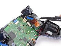
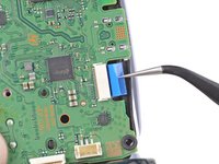
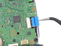
Use a pair of tweezers or your fingers to grip the touchpad ribbon cable pull tab, and pull it straight out of the motherboard connector.
-
-
-
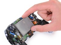
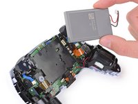
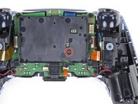
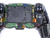
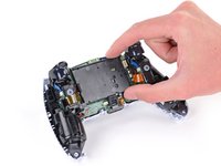
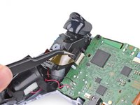
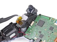
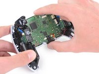
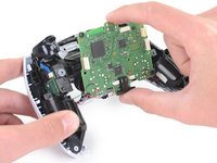
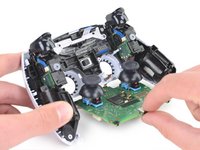
Carefully guide the joysticks through the front case and lift the motherboard out.
-
The motherboard is held down by two clips. One between the motherboard itself and the right trigger assembly, and one between the motherboard itself and the left trigger assembly. Gently push on either clip to release the motherboard from its restraints.
-
-
Tool used on this step:FixHub Smart Soldering Iron$79.95
-
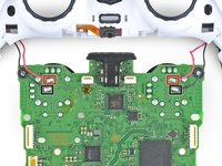
Flip over the controller and motherboard.
-
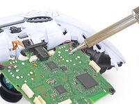
Use a soldering iron to desolder the vibration motor wires from the motherboard:
-
Two red wires
-
Two black wires
-
-
-
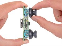
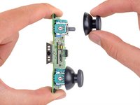
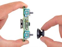
Pull the joystick covers straight off the joystick assemblies.
-
Only the motherboard remains.
-


To reassemble your device, follow the above steps in reverse order.
Take your e-waste to an R2 or e-Stewards certified recycler.
Repair didn’t go as planned? Try some basic troubleshooting, or ask our Answers community for help.
Cancel: I did not complete this guide.
17 other people completed this guide.

4 Guide Comments
Where can you buy a new motherboard in the UK?
Cool tutorial, all we need now is to know which chip slows the input 5v current to only push 1.5A then we would be able to get a service which can enable fast charge. Karl brook.
what size capacitors are used near the toggle controller, there is one near the right joystick and another by the left joystick at the bottom right.
any help would be apreciated.
Donde compro la tarjeta base?