Introduction
This guide gives you a look at the major components of the Olympus Pen E-PL7 and provides complete disassembly instructions.
We highly suggest you use a magnetic project mat or an organization tray. This camera has many different types of screws and keeping them organized is key to proper reassembly.
What you need
-
-
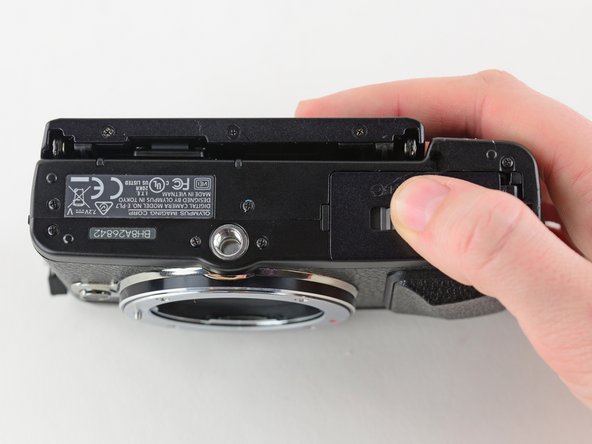
Turn the camera upside down.
-
Push the grey tab to the right to open the battery compartment.
-
Pull out the battery.
-
-
-
Use a Phillips #00 screwdriver to remove the six 2 mm screws on the bottom of the camera.
-
-
-
Flip open the LCD.
-
Use a Phillips #00 screwdriver to remove the 2 mm screw beneath the LCD assembly.
-
-
-
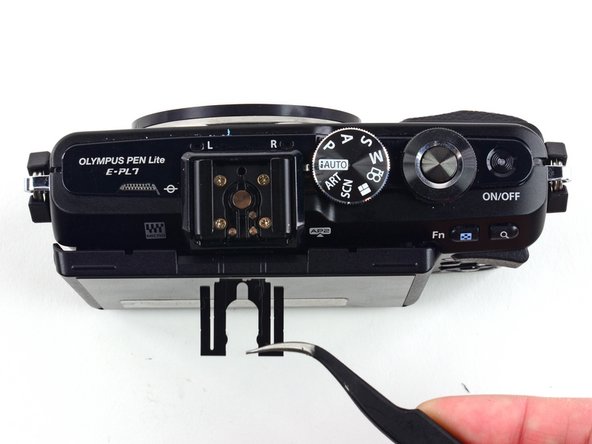
Press and hold the lens release button while using tweezers to remove the lens hook.
-
Use tweezers to remove the spring underneath the lens hook.
-
-
-
Use a Phillips #00 screwdriver to remove the two 6.4 mm screws.
-
Remove the 2 mm Phillips screw.
-
-
-
-
To remove the ribbon holding the back case to the camera, use the pointed end of a spudger to flip back the top bar on top of the ZIF connector.
-
-
-
Use a Phillips #00 screwdriver to remove the two 1.6 mm screws near the left hand grip.
-
-
-
Remove the 2.2 mm Phillips screw near the left hand grip, holding a second metal plate in place.
-
Remove the 1.8mm Phillips screw.
-
-
-
Use a spudger to remove the three indicated ribbon cables from their ZIF connectors on the motherboard.
-
-
-
Use tweezers to remove the plastic cover from the two ZIF connectors in the upper left corner of the motherboard.
-
Disconnect both ribbon cables.
-
-
-
Desolder the large ribbon cable from the motherboard at the solder points on either side of its ZIF connector
-
Learn more about soldering with iFixit's Soldering Tecnique Guide.
-
-
-
Remove the two 4.3 mm screws from the front of the sensor assembly.
-
Remove the 6.8 mm screw.
-
-
-
Remove the four 1.9mm Phillips screws from the back of the sensor assembly.
-
Remove the 14.5mm Phillips screw.
-
Remove the 3.3mm Phillips screw.
-
-
-
Use a Phillips #00 screwdriver to remove the 1.7 mm screw securing the tripod mount to the ribbon cable.
-
Use tweezers to remove the small copper ring underneath the screw.
-
-
-
Remove the 4.4 mm Phillips screw securing the motherboard to the battery compartment.
-
Remove the 3.8 mm Phillips screw.
-
Remove the 3.7mm Phillips screw.
-
-
-
Use a Phillips #00 screwdriver to remove the three 2.3 mm screws from the base of the LCD screen.
-
-
-
Remove the two 2.2 mm Phillips screws located on the back of the LCD screen.
-
Use tweezers to remove the top bracket.
-
-
-
Use a Phillips #00 screwdriver to remove the four 1.4 mm screws from the back of the LCD screen.
-
Remove the LCD ribbon cable with a pair of tweezers.
-