
Battery Disconnect

Prerequisite Only
This is a prerequisite-only guide! This guide is part of another procedure and isn’t meant to be used alone.

What you need

  1. Battery Disconnect, Before you begin: step 1, image 1 of 3 Battery Disconnect, Before you begin: step 1, image 2 of 3 Battery Disconnect, Before you begin: step 1, image 3 of 3
    • Before starting this repair, allow your laptop's battery to drain below 25%. A charged battery may catch fire if damaged.

    • Unplug all cables and fully shut down your laptop.

  2. Battery Disconnect, Open the kickstand: step 2, image 1 of 3 Battery Disconnect, Open the kickstand: step 2, image 2 of 3 Battery Disconnect, Open the kickstand: step 2, image 3 of 3
    • Lay your Surface Pro screen side down and open the kickstand to about a 90‑degree angle.

  3. Battery Disconnect, Remove the SSD screw: step 3, image 1 of 2 Battery Disconnect, Remove the SSD screw: step 3, image 2 of 2
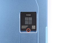
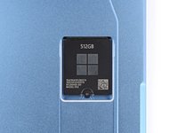
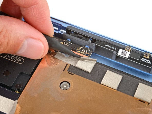
    • Use a Torx Plus 3IP screwdriver to remove the 2.4 mm‑long screw securing the SSD.

    • Removing the SSD also functions as a battery disconnect and should be done before all major repairs.

  4. Battery Disconnect, Remove the SSD: step 4, image 1 of 3 Battery Disconnect, Remove the SSD: step 4, image 2 of 3 Battery Disconnect, Remove the SSD: step 4, image 3 of 3
    • Don't pull up at a sharp angle, or you may damage the SSD and its socket.

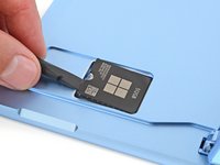
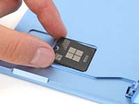
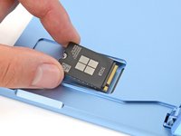
    • Use the flat end of a spudger to gently lift the notched edge of the SSD enough that you can grip the bottom corners with your fingers.

    • Use your fingers or tweezers to pull the SSD straight out of its socket and remove it.

    • During reassembly, getting the SSD fully inserted in its socket can be tricky. If you're having trouble, hold the SSD in place and use the flat end of a spudger to push on the notched edge.

  5. Battery Disconnect, Remove the SSD door: step 5, image 1 of 3 Battery Disconnect, Remove the SSD door: step 5, image 2 of 3 Battery Disconnect, Remove the SSD door: step 5, image 3 of 3
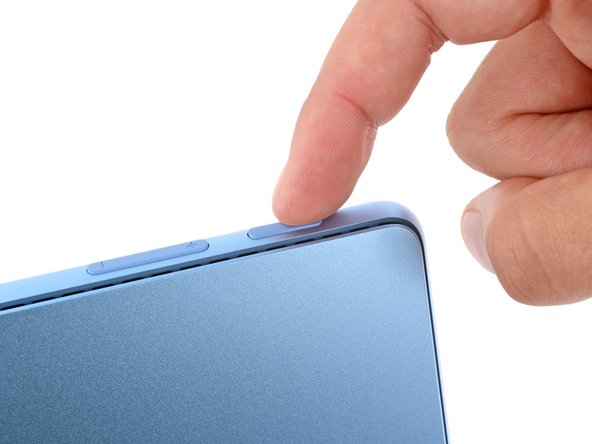
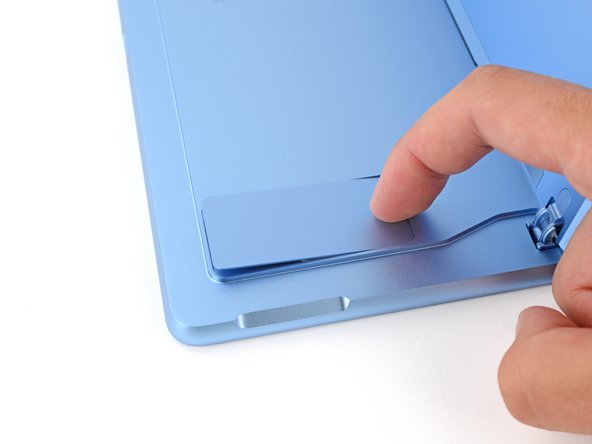
    • Use your finger to firmly press down on the SSD door indent until the door pops up.

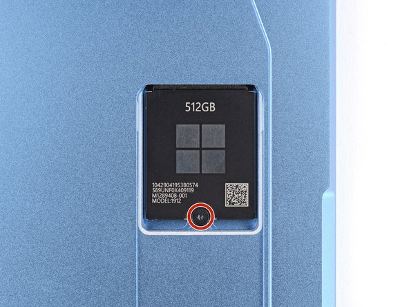
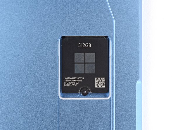
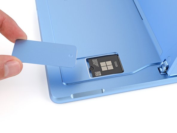
    • Remove the SSD door.

  6. Battery Disconnect, Adhesive information: step 6, image 1 of 3 Battery Disconnect, Adhesive information: step 6, image 2 of 3 Battery Disconnect, Adhesive information: step 6, image 3 of 3
    • When separating the screen from the frame, don't insert your tool more than the following measurements on the given edges. Otherwise, you may damage your device's internals.

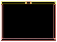
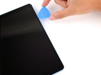
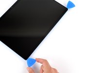
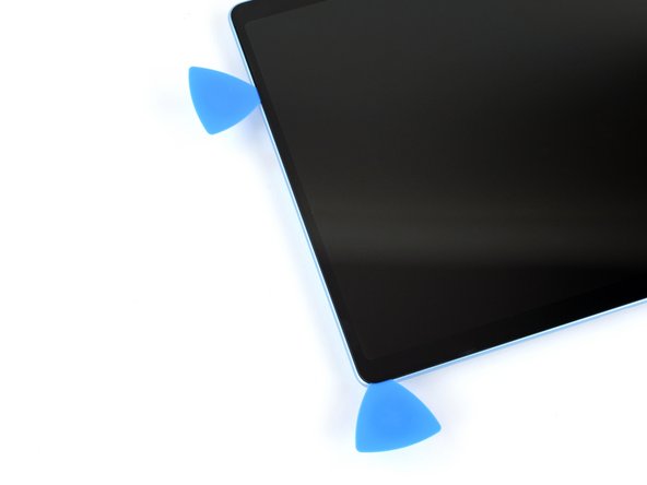
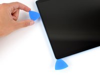
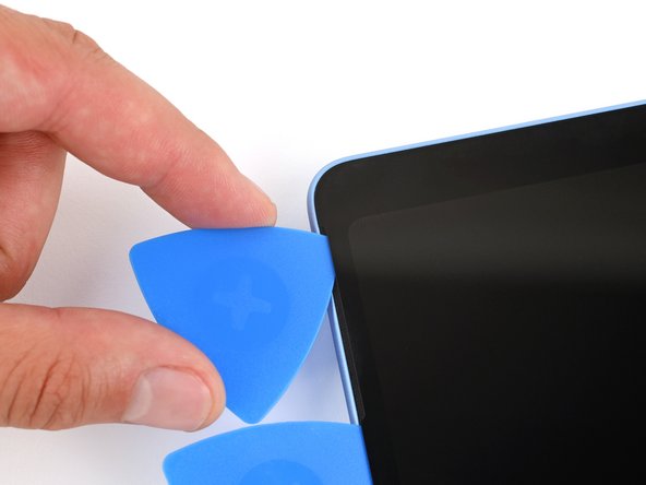
    • 2 mm on the left, right, and bottom edges

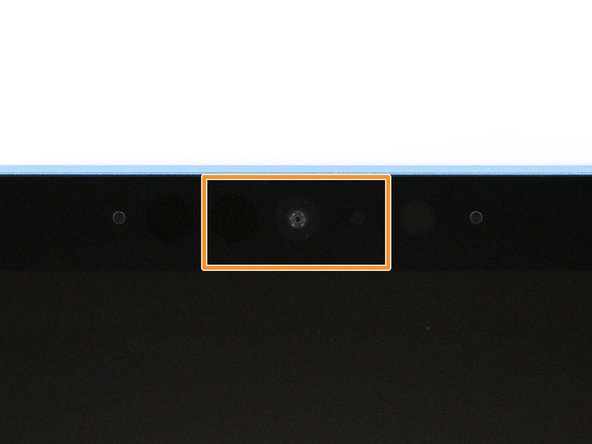
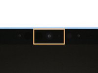
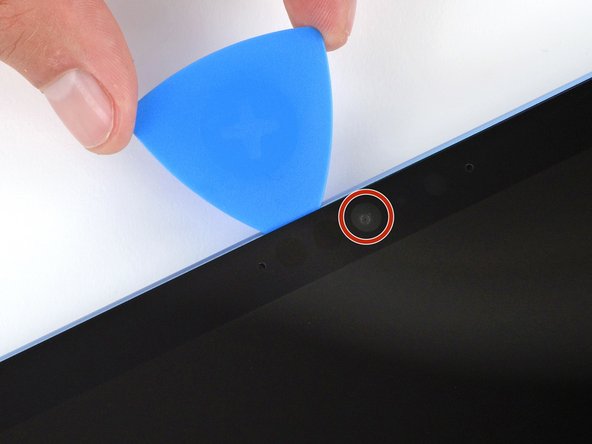
    • Don't insert your tool at all near the front facing camera on the top edge

    • 8 mm along the top edge (everywhere besides the front facing camera area)

  7. Battery Disconnect, Heat the right edge: step 7, image 1 of 1
    • Mild adhesive secures the perimeter of the screen to the frame. Heating the screen will soften the adhesive, making it easier to separate.

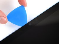
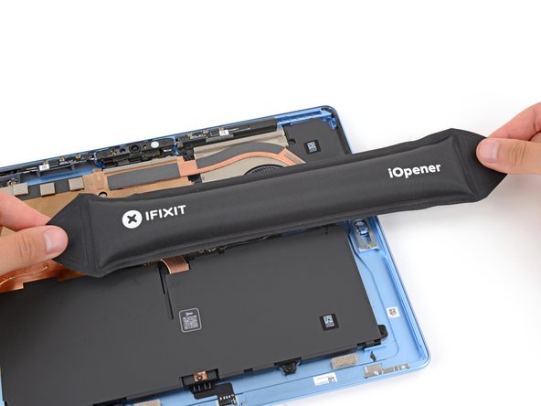
    • Heat an iOpener and lay it on the right edge of the screen for two minutes to soften the adhesive.

    • Alternatively, you can use a hair dryer or heat gun. But be careful, as the screen and battery are susceptible to heat damage.

  8. Battery Disconnect, Separate the right edge adhesive: step 8, image 1 of 3 Battery Disconnect, Separate the right edge adhesive: step 8, image 2 of 3 Battery Disconnect, Separate the right edge adhesive: step 8, image 3 of 3
    • Remember not to insert your pick more than 2 mm on the right edge.

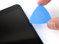
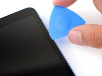
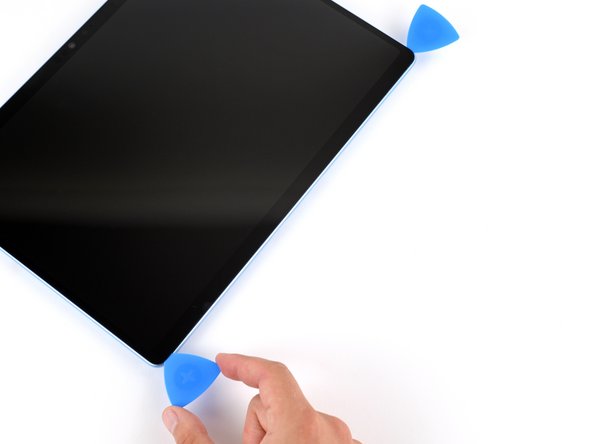
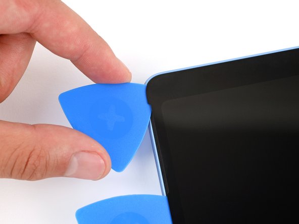
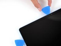
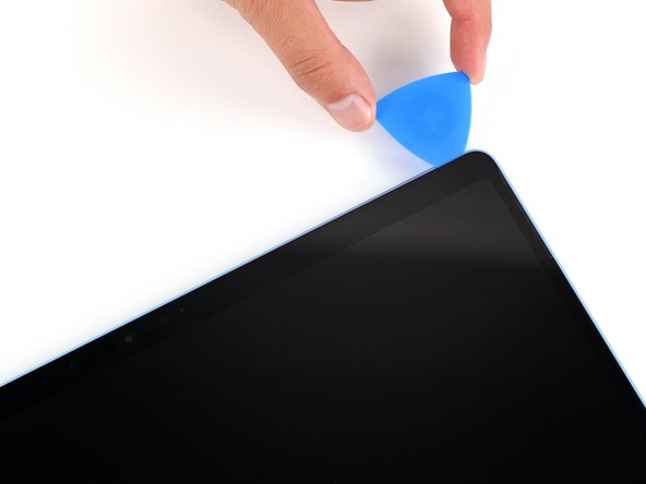
    • Insert the tip of an opening pick under the screen near the bottom of the right speaker cutout.

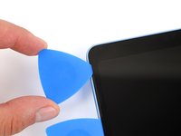
    • Slide your pick towards the bottom edge and slightly rotate it so the tip goes under the notch in the screen.

  9. Battery Disconnect: step 9, image 1 of 3 Battery Disconnect: step 9, image 2 of 3 Battery Disconnect: step 9, image 3 of 3
    • Slide your pick down the right edge to separate the adhesive securing it.

    • Leave your pick inserted under the bottom right corner to prevent the adhesive from re‑sealing.

  10. Battery Disconnect, Heat the bottom edge: step 10, image 1 of 1
  11. Battery Disconnect, Separate the bottom edge adhesive: step 11, image 1 of 3 Battery Disconnect, Separate the bottom edge adhesive: step 11, image 2 of 3 Battery Disconnect, Separate the bottom edge adhesive: step 11, image 3 of 3
    • Remember not to insert your pick more than 2 mm on the bottom edge.

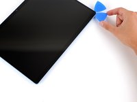
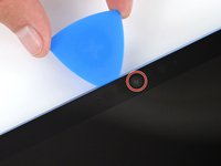
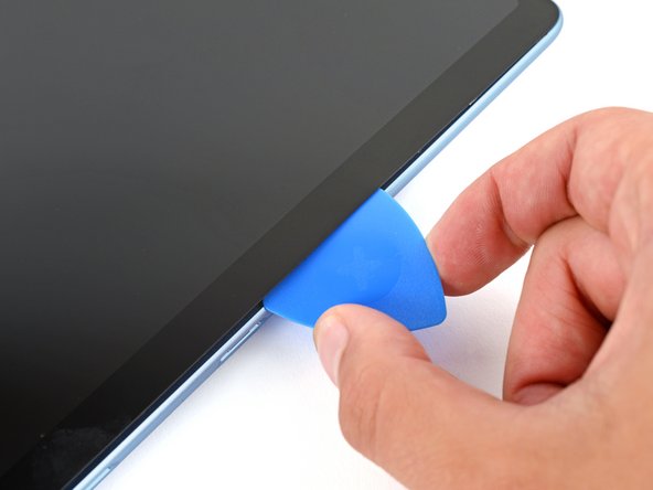
    • Insert a second pick under the bottom right corner of the screen and slide it along the bottom edge to separate the adhesive.

    • Leave your second pick inserted under the bottom left corner to prevent the adhesive from re‑sealing.

  12. Battery Disconnect, Heat the left edge: step 12, image 1 of 1
  13. Battery Disconnect, Separate the left edge adhesive: step 13, image 1 of 3 Battery Disconnect, Separate the left edge adhesive: step 13, image 2 of 3 Battery Disconnect, Separate the left edge adhesive: step 13, image 3 of 3
    • Remember not to insert your pick more than 2 mm on the right edge.

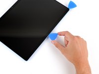
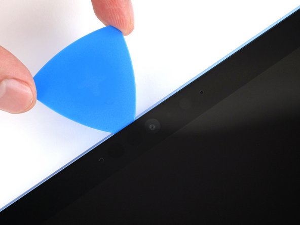
    • Insert a third pick under the bottom left corner of the screen and slide it up the left edge, stopping when you get to the bottom of the left speaker cutout.

    • Leave the pick inserted under the screen to prevent the adhesive from re-sealing.
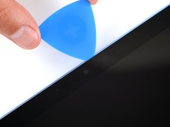
  14. Battery Disconnect, Heat the top edge: step 14, image 1 of 1
  15. Battery Disconnect: step 15, image 1 of 3 Battery Disconnect: step 15, image 2 of 3 Battery Disconnect: step 15, image 3 of 3
    • Insert a fourth pick under the screen near the top of the left speaker cutout.

    • Slide your pick towards the top edge and slightly rotate it so the tip goes under the notch in the screen.

  16. Battery Disconnect, Separate the top edge adhesive: step 16, image 1 of 3 Battery Disconnect, Separate the top edge adhesive: step 16, image 2 of 3 Battery Disconnect, Separate the top edge adhesive: step 16, image 3 of 3
    • Remember not to insert your pick more than 8 mm on the top edge.

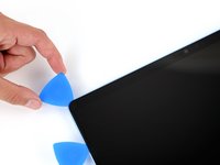
    • Slide the pick along the top edge and stop before you get to the front facing camera.

  17. Battery Disconnect: step 17, image 1 of 3 Battery Disconnect: step 17, image 2 of 3 Battery Disconnect: step 17, image 3 of 3
    • Be very careful not to touch the front facing camera lens with your tool.

    • Remove the pick enough that it can pass above the front facing camera.

    • Slide the pick along the top edge until it's past the camera.

  18. Battery Disconnect: step 18, image 1 of 3 Battery Disconnect: step 18, image 2 of 3 Battery Disconnect: step 18, image 3 of 3
    • Insert your pick 8 mm under the screen and slide it to the top right corner to separate the remaining adhesive.

  19. Battery Disconnect, Separate the screen: step 19, image 1 of 3 Battery Disconnect, Separate the screen: step 19, image 2 of 3 Battery Disconnect, Separate the screen: step 19, image 3 of 3
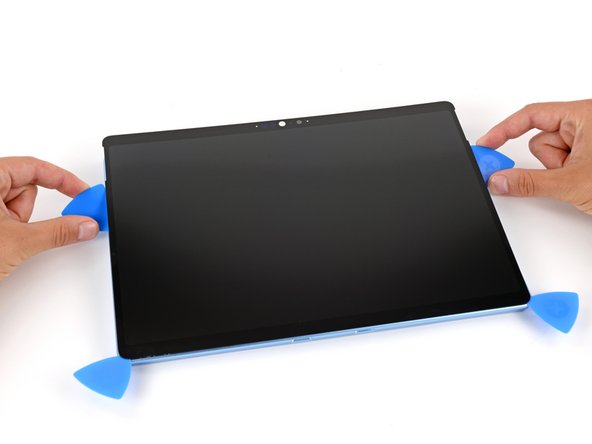
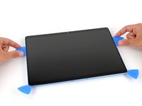
    • Insert the flat edge of two picks under the screen, below the two speaker cutouts.

    • Use the picks to gently pry up the screen, fully separating it from the frame.

    • Don't try to remove the screen yet, as a ribbon cable still connects it to your device.

    • If the screen feels stuck anywhere, use your pick to separate the adhesive in that area. Remember not to insert your pick too far under the screen.

  20. Battery Disconnect, Flip the screen over: step 20, image 1 of 3 Battery Disconnect, Flip the screen over: step 20, image 2 of 3 Battery Disconnect, Flip the screen over: step 20, image 3 of 3
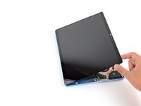
    • Once the screen is fully separated, flip the top edge over the bottom edge and lay the screen down flat, being careful not to strain the ribbon cable.

  21. Battery Disconnect, Remove the screen cable shield: step 21, image 1 of 3 Battery Disconnect, Remove the screen cable shield: step 21, image 2 of 3 Battery Disconnect, Remove the screen cable shield: step 21, image 3 of 3
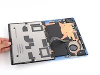
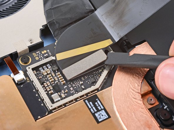
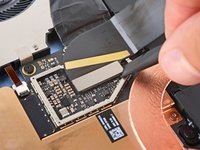
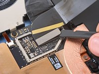
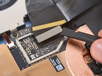
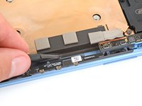
    • Use the tip of a spudger to lift the conductive tape off the copper shield, near the center of your device.

  22. Battery Disconnect: step 22, image 1 of 3 Battery Disconnect: step 22, image 2 of 3 Battery Disconnect: step 22, image 3 of 3
    • Insert an arm of a pair of angled tweezers in one of the gaps on the edge of the screen cable shield.

    • Use your tweezers to gently pry up and remove the shield.

    • Try to deform the shield as little as possible—you'll reuse it during reassembly.

  23. Battery Disconnect, Disconnect the screen: step 23, image 1 of 3 Battery Disconnect, Disconnect the screen: step 23, image 2 of 3 Battery Disconnect, Disconnect the screen: step 23, image 3 of 3
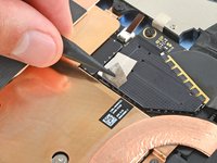
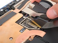
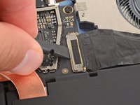
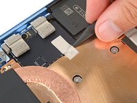
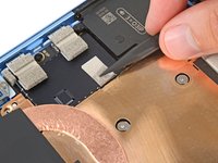
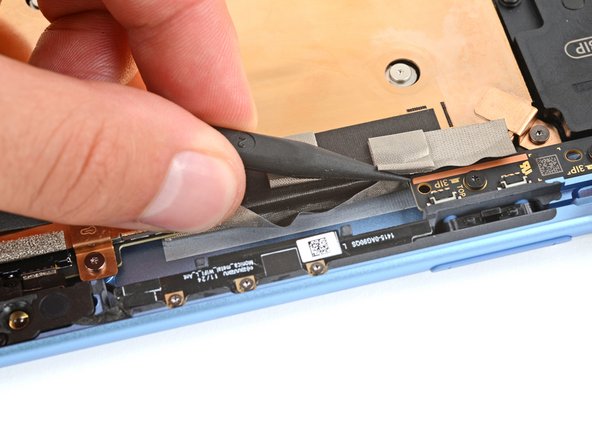
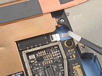
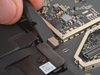
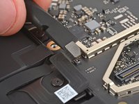
    • Insert the flat end of a spudger under the notched corner of the screen cable press connector and pry up to disconnect it.

  24. Battery Disconnect, Remove the screen: step 24, image 1 of 1
    • Grip the screen with both hands and remove it.

    • During reassembly, follow this guide to replace the screen adhesive and install your screen.

  25. Careful: steps 25-30 are sourced from a guide that's marked as in-progress.

    Battery Disconnect, Disconnect the Surface Connect port: step 25, image 1 of 3 Battery Disconnect, Disconnect the Surface Connect port: step 25, image 2 of 3 Battery Disconnect, Disconnect the Surface Connect port: step 25, image 3 of 3
    • Use the flat end of a spudger or a clean fingernail to flip up the metal buckle on the Surface Connect port cable.

  26. Battery Disconnect: step 26, image 1 of 2 Battery Disconnect: step 26, image 2 of 2
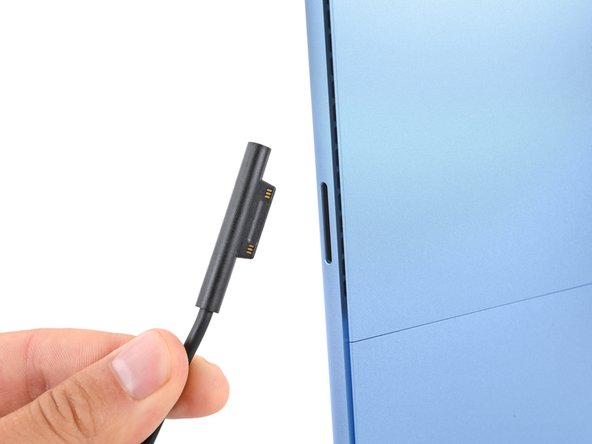
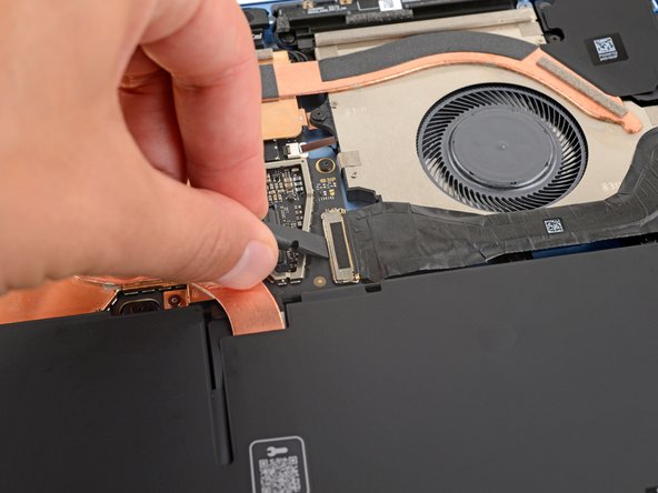
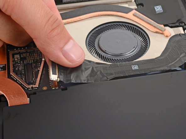
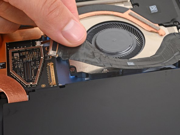
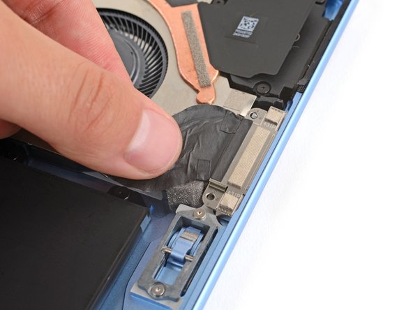
    • Use tweezers or your fingers to firmly grip the Surface Connect port cable close to the connector head and pull it straight out of the socket.

    • During reassembly:

    • Remove any adhesive liners from the Surface Connect port cable or bottom edge of the fan.

    • Use tweezers or your fingers to insert the cable's connector into its socket.

    • Flip the metal buckle over the connector and firmly press around its perimeter until it snaps into place.

    • Firmly press the cable into place on the fan to secure it with the adhesive.

  27. Battery Disconnect, Remove the Surface Connect Port screws: step 27, image 1 of 2 Battery Disconnect, Remove the Surface Connect Port screws: step 27, image 2 of 2
    • Use a Torx Plus 3IP screwdriver to remove the two 3.6 mm‑long screws securing the Surface Connect port to the frame.

  28. Battery Disconnect, Separate the Surface Connect port cable: step 28, image 1 of 1
    • Mild adhesive secures the Surface Connect port cable to the bottom edge of the fan.

    • Heat an iOpener and lay it on the Surface Connect port cable for two minutes to soften the adhesive.

    • Alternatively, you can use a hair dryer or heat gun to lightly heat the cable. But be careful, as the battery is susceptible to heat damage.

  29. Battery Disconnect: step 29, image 1 of 2 Battery Disconnect: step 29, image 2 of 2
    Tool used on this step:
    Tesa 61395 Tape
    $2.99
    Buy
    • Grip the Surface Connect cable by the end with the motherboard connector and peel the cable from the fan.

    • During reassembly:

    • Don't secure the Surface Connect port cable with adhesive yet—wait until you've reconnected it. Otherwise, the cable may not reach its socket if positioned incorrectly.

    • If you're reinstalling the original port, the adhesive should be sticky enough to reuse.

    • If the adhesive isn't sticky enough, or if you're installing a new port and it doesn't come with adhesive pre‑installed, apply a strip of thin, double‑sided tape to the bottom edge of the fan (not the cable). If your tape has a liner on top, don't remove it.

  30. Battery Disconnect, Remove the Surface Connect Port: step 30, image 1 of 2 Battery Disconnect, Remove the Surface Connect Port: step 30, image 2 of 2
    • Lift the Surface Connect port out of its recess in the frame and remove it.

    • During reassembly:

    • Put the Surface Connect port into place so its cutouts go over their frame posts. Make sure the port is fully in its cutout—the outer edge should be flush with the frame.

    • Install the two screws that secure the port.
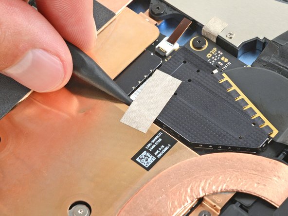
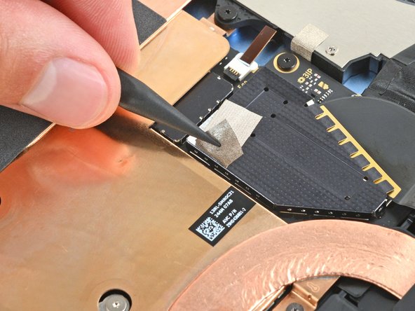
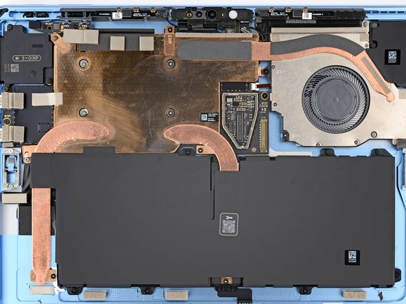
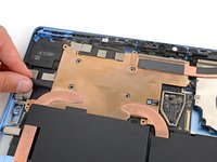
    • The screws will be drawn to the magnet in the port. You may need to use a pair of tweezers to hold them in place.

  31. Careful: steps 31-37 are sourced from a guide that's marked as in-progress.

    Battery Disconnect, Detach the thermal module tape: step 31, image 1 of 3 Battery Disconnect, Detach the thermal module tape: step 31, image 2 of 3 Battery Disconnect, Detach the thermal module tape: step 31, image 3 of 3
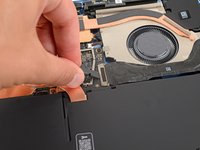
    • Use the point of a spudger to lift the two pieces of silver conductive tape from the top left corner of the thermal module.

  32. Battery Disconnect: step 32, image 1 of 3 Battery Disconnect: step 32, image 2 of 3 Battery Disconnect: step 32, image 3 of 3
    • Use the point of a spudger to lift the black conductive tape on the thermal module's top edge, detaching it from the frame.

  33. Battery Disconnect, Disconnect the fan: step 33, image 1 of 3 Battery Disconnect, Disconnect the fan: step 33, image 2 of 3 Battery Disconnect, Disconnect the fan: step 33, image 3 of 3
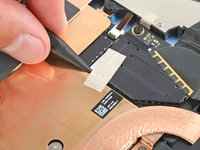
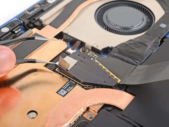
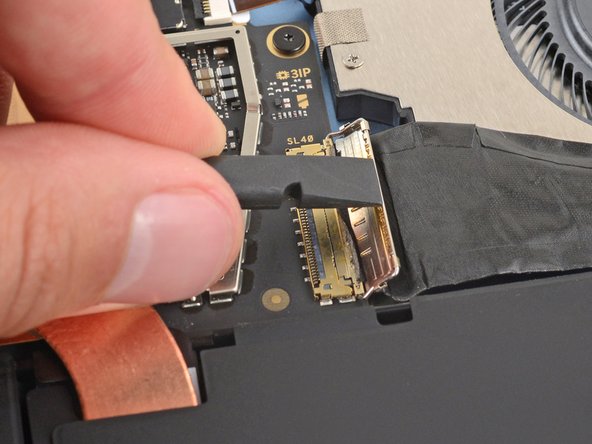
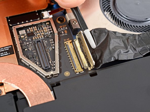
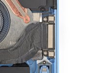
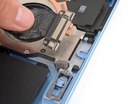
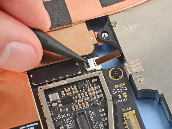
    • Use the point of a spudger to lift the black locking flap on the fan cable ZIF connector, near the center of the fan's left edge.

    • Use tweezers to grip the cable's plastic pull tab and gently slide the cable out of its socket.

  34. Battery Disconnect, Remove the thermal module and fan screws: step 34, image 1 of 2 Battery Disconnect, Remove the thermal module and fan screws: step 34, image 2 of 2
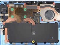
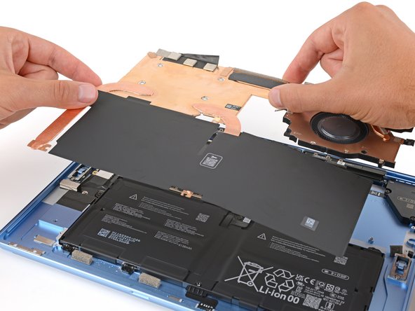
    • Use a Torx Plus 3IP screwdriver to remove the 14 screws securing the thermal module and fan assembly:

    • Eight 2.6 mm‑long screws

    • One 2.8 mm‑long screw near the top of the fan's left edge

    • One 3.7 mm‑long screw near the center of the battery's bottom edge

    • Four 2.4 mm‑long CPU tension screws in the center of the thermal module

    • During reassembly, first install the four CPU tension screws in an "X" pattern. For example: top left, bottom right, top right, bottom left.

  35. Battery Disconnect, Separate the thermal module: step 35, image 1 of 3 Battery Disconnect, Separate the thermal module: step 35, image 2 of 3 Battery Disconnect, Separate the thermal module: step 35, image 3 of 3
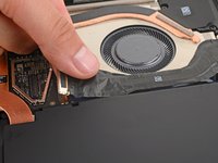
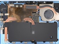
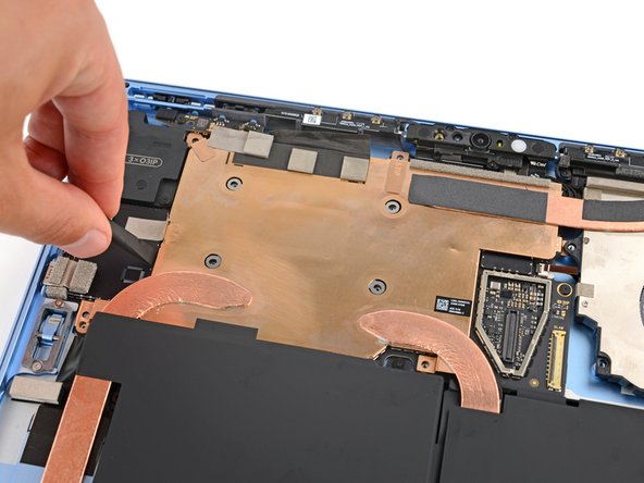
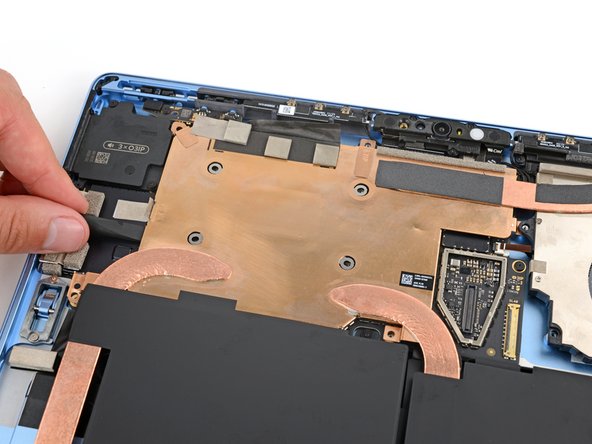
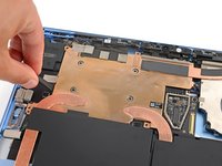
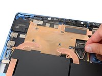
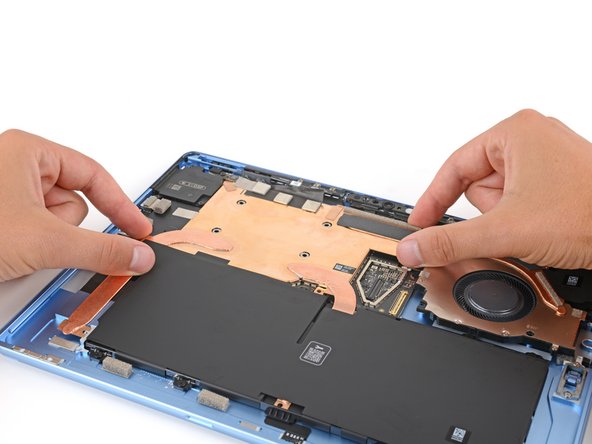
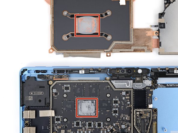
    • Use the flat end of a spudger to pry up the left and right edges of the thermal module, near where the copper heat pipes bend.

    • Thermal paste bonds the thermal module to the motherboard. Depending on the age of your laptop and condition of the paste, this may take some force.

  36. Battery Disconnect: step 36, image 1 of 2 Battery Disconnect: step 36, image 2 of 2
    • Don't lift the assembly by the fan or you risk bending the thermal module.

    • Use two hands to lift the thermal module straight up and remove it.

  37. Battery Disconnect, Thermal paste replacement: step 37, image 1 of 3 Battery Disconnect, Thermal paste replacement: step 37, image 2 of 3 Battery Disconnect, Thermal paste replacement: step 37, image 3 of 3
    Tool used on this step:
    iFixit Thermal Paste
    $9.95
    Buy
    • During reassembly:

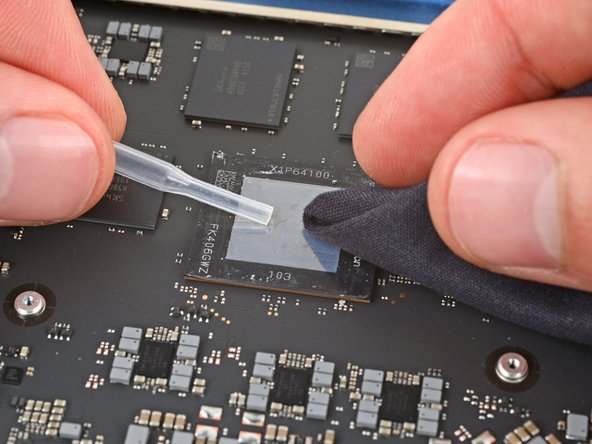
    • If you're installing a new thermal module, check if the bottom has thermal paste pre‑installed. If it does, do not apply thermal paste—you only need to clean the CPU.

    • Follow this guide to clean the thermal module and CPU and apply thermal paste.

    • If you're installing a new thermal module, you don't need to clean it.

  38. Battery Disconnect, Disconnect the battery: step 38, image 1 of 3 Battery Disconnect, Disconnect the battery: step 38, image 2 of 3 Battery Disconnect, Disconnect the battery: step 38, image 3 of 3
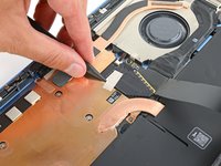
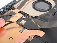
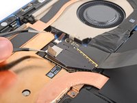
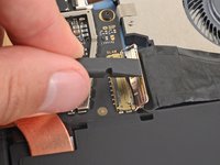
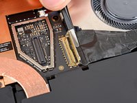
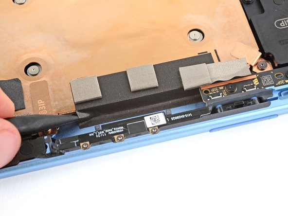
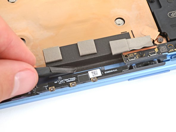
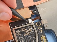
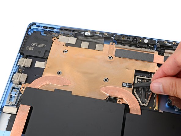
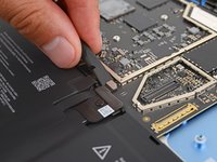
    • Use the flat end of a spudger to pry up the battery press connector from a short edge and disconnect it.

    • Prying from the long edge risks damaging the connector and socket.

Finish Line

Spencer Day

Member since: 09/14/22

155,806 Reputation

1,033 Guides authored

Team

iFixit Member of iFixit

Staff

123 Members

23,828 Guides authored

0 Guide Comments

Add Comment

View Statistics:

Past 24 Hours: 0

Past 7 Days: 0

Past 30 Days: 0

All Time: 63