08. LCD screen and PSU

Last updated on Nov 5, 2026
Views: 41
View statistics:
- Past 24 Hours:
- 3
- Past 7 Days:
- 41
- Past 30 Days:
- 41
- All Time:
- 41
Comments: 0
No one has left comments on this guide. Will you be first?
Go to guide commentsCompleted: 0 1
No one has marked this guide "completed." Will you be the first?
1 person has marked this guide "completed." It's you — great job!
Favorites: 0 1
No one has favorited (and subscribed to) this guide. Will you be the first?
1 person has favorited (and subscribed to) this guide — and that's you!
-
-
-
Slide the lcd_support_a and lcd_support_b onto the LCD control board.
-
Assemble the LCD cover on the LCD control board.
-
Adjust the position of the lcd_support_a and lcd_support_b in order to insert the LCD control board on the cover.
-
The LCD control board must clip into the LCD cover.
-
Secure the LCD control board with 2x M3x10 screws (reused from your Original Prusa).
-
Put the LCD knob back in place.
 Ask FixBot
-
-
-
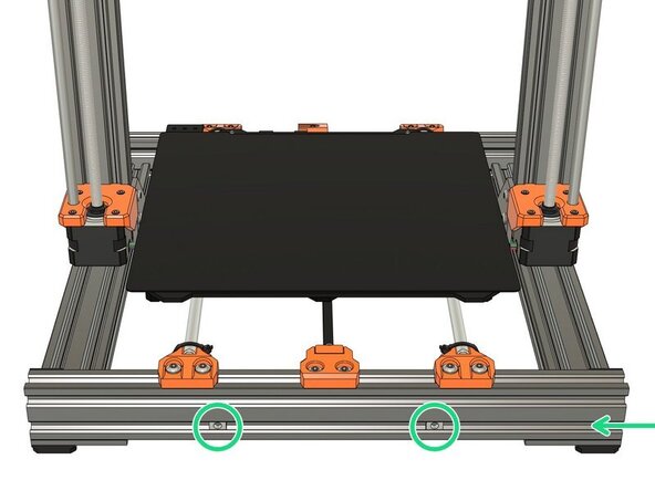
Slide 2x t-nuts in the bottom front of your frame.
-
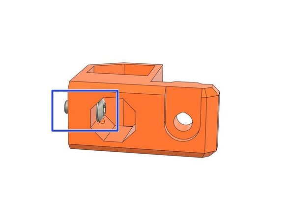
Attach the LCD using 2x M5x10 screws.
-
-
-
Prepare the following hardware:
-
2x M4x10 screws (reused from your Original Prusa).
-
2x psu_upper_mount.
-
Place the M4x10 screw in the internal hole of the psu_upper_mount.
-
Insert the other M4x10 in the remaining psu_upper_mount.
-
Now try not to lose the screws until we are bolting them on the PSU :D
-
-
-
The next steps are for the Prusa silver PSU only.
-
If you have the Prusa black PSU, go to step 11
-
Prusa black PSU
-
Prusa silver PSU
-
-
-
Attach the psu_upper_mounts to the silver PSU body. Fully tighten the M4 screws, ensuring that the PSU mounts are properly positioned and aligned .
-
Verify that the psu_upper_mounts are aligned with the PSU
-
-
-
Take the psu_lower_mount and insert a square nut.
-
Slide 1x t-nut into the lower channel of the rear extrusion, from the right side of the frame.
-
Assemble the psu_lower_mount with 1x M5x10 screw. Don't tighten fully yet as it will need some repositioning.
-
-
-
-
Rotate the frame to the right side. Carefully guide the extruder to the right. Do not let it slide freely into the x-ends..
-
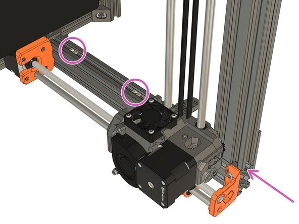
Slide 2x t-nuts into the extrusion from the top of the frame, as shown.
-
Position the PSU and secure it with 2x M5x10 screws. Do not tighten them fully yet.
-
-
-
Secure the bottom of the PSU with an M3 screw reused from your Original Prusa, do not tighten fully yet. This screw has a different length depending on which Prusa model you have:
-
MK2(S) or MK2.5(S): length can be 18mm or 25mm (both are compatible with the psu_lower_mount).
-
MK3(S): 10mm long.
-
Verify that the PSU cables are not pinched and pass under the Y axis smooth rod.
-
Adjust the PSU position to be flush with the extrusion at the rear of the frame.
-
Fully tighten evenly, incrementally and in turn the screws of psu_lower_mount and psu_upper_mount.
-
-
-
Congratulations you have finished this chapter :)
-
Go to the next chapter: 09. Electronics assembly.
-
-
-
The next steps are for the Prusa black PSU only.
-
If you have the Prusa silver PSU, go to step 5
-
Prusa black PSU
-
Prusa silver PSU
-
-
-
Attach the psu_upper_mounts to the black PSU body. Fully tighten the M4 screws, ensuring that the PSU mounts are properly positioned and aligned .
-
Verify that the psu_upper_mounts are aligned with the PSU
-
-
-
Take the psu_lower_mount and insert a square nut.
-
Slide 1x t-nut into the top channel of the rear extrusion, from the right side of the frame.
-
Assemble the psu_lower_mount with 1x M5x10 screw. Don't tighten fully yet as it will need some repositioning.
-
-
-
Rotate the frame to the right side. Carefully guide the extruder to the right. Do not let it slide freely into the x-ends..
-
Slide 2x t-nuts into the extrusion from the top of the frame, as shown.
-
Position the PSU and secure it with 2x M5x10 screws. Do not tighten them fully yet.
-
-
-
Remove the PSU cover (with Prusa logo) by unscrewing the 2x M3x10 screws.
-
Take an extra M3x10 (reused from your Original Prusa) screw and secure the PSU to the psu_lower_mount. Do not tighten fully yet.
-
Verify that the PSU cables are not pinched and that they go out of the back of the PSU and pass under the Y axis smooth rod.
-
-
-
Adjust the PSU position to be flush with the extrusion at the rear of the frame.
-
Fully tighten evenly, incrementally and in turn the screws of psu_lower_mount and psu_upper_mount.
-
Reassemble the PSU cover with 2x M3x10 screws (reused from your Original Prusa).
-
-
-
Congratulations you have finished this chapter :)
-
Go to the next chapter: 09. Electronics assembly.
-
-