
Free Shipping on Domestic Orders $75+

Guides and support for various television (TV) brands and styles.

Red Light Continuous Blink - Celcus LED TV

Model: 40913LED

Brand: Celcus

No issues with TV for 3 years. Last weekend I unplugged from mains with firestick still attached and replugged after 24h. Since then I get the standby light blinking red at 1/s frequency and the screen doesn't turn on.

When I press buttons on the TV I still get a bleep, but nothing happens.

Steps attempted:
disconnect everything except power cable

leave unplugged for >1h and retry

press for 30s power+menu, power+volume, power+remote red

reconnect firestick and retry

Shine light on screen: no images/motion seen

Inspect PSU and motherboard - no obvious damaged components

I've borrowed a multimeter for the weekend and was hoping for some help on what to test? Hopefully the problem is in the PSU. I'll attach pictures of the boards.

Block Image
Block Image

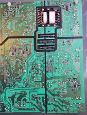
PCU: 17PW07-2 080411 V1

Block Image
Block Image
Block Image

Main AV board: 17MB65S-2 210711

Block Image

LED driver board: SSL400_0E2B - REV0.1

EDIT 14/10:
I've tested the connectors with the TV plugged as suggested below.
PIN NUMBER(voltage)
connector PL205 1(0.01),2(0.01),3(0.07),4(0.01),5(0.02),6(0.02),7(0.02),8(0.01),9(3.33),10(0.01),11(12),12(12),13(4.3),14(0.03),15(4.3),16(4.3),17(3.4),18(5),19(3.4),20(5),21(3.4),22(5),23(0.03),24(0.02),25(24.3),26(2.62*),27(0.08),28(0.6)

connector PL306 1(24.5),2(24.5),3(24.5),4(24.5),5(24.5**),6(0),7(0),8(0),9(0),10(0),11(3.3),12(0.02)

*shorted by mistake 26 and 25. after that 26 voltage permanently changed from 2.6 to 0.4

  • spark when testing 5, pretty sure it wasn't shorting with anything. voltage changed from 25V to 0.02V and standby light went from blinking to steady. after unplugging and plugging back in voltage reverted back to 25V

Also had big spark when testing diode D215, but after unplugging still testing the same as D228

Different on connector PL205: 13,14,25,26. This is comparing with the schematic provided below, which isn't exactly the same as the PSU I have.

What's the next step? Can you diagnose the problem from these results?

EDIT16/10

Zoom image

Block Image
Answer this question I have this problem too

Is this a good question?

Score 1
Add a comment

1 Answer

Most Helpful Answer

@tvi whatever you need to try, you want to do that without the Firestick. You'll be surprised about what errors those can sometimes cause.

This sounds very much like a power board issue. We would need you to measure the voltages on your power supply connector PL205. Here is the trick, you will have to do that with the power connected. Do not touch your boards with your bare hands. Only use the probes from the multimeter. Black to ground and Red to probe the contacts. Some of those contacts can be hard to come by. Make sure that you use needle probes and/or measure the pins on the underside of the board.

Again, two things to be aware off. Do not touch the board and do not cross contacts with the probes. You ready? :-) Here is the schematic for your power board.Vestel 17pw07 2 Page 1 bottom right shows the connector and lists the corresponding voltages. Measure those and let us know what you find out.

Was this answer helpful?

Score 1

5 Comments:

So far I've made sure all capacitors were discharged, tested the fuse on the PSU and tested all the diodes. Everything was OK except 2 diodes that had higher value on the reverse reading, but from what I understand there are different types and that could be as intended.

Regarding your schematic, it seems to be for a different variant with 2 fuses instead of 1. It also says 290311 vs 080411 V1 on my board. I'm not competend enough to see if there's any significant differences that will alter the readings.

Before testing, I just want to clarify a few things:

Black to ground - can this be the metal chassis of the TV?

Do I have to keep the other boards connected to the PSU? Or can I disconnect them and place the PSU in a rubber mat?

I don't have needle probes, can I test the corresponding connector terminals on the AV board? I feel more confident about flipping that board since it isn't live

by

@tvi Black to ground - can this be the metal chassis of the TV? Yes, if you keep the board in the TV.

Do I have to keep the other boards connected to the PSU? Yes you do. It is the main board that tells the power board to turn on. If you disconnect the other boards, the only voltage your power board should show, is the standby voltage. That is the problem with having to test a "live" board. It has to be connected to the rest of the TV.

In the past, I have created my own needle probes by just attaching sewing needles to the thicker probe ends :-)

by

Please see my edited post for the voltage results

by

@tvi your stby voltage seem high at 25V and it should not shorten out when you measure it. Post another picture of you power board. This time focus on the right top quadrant. Make sure it is well focused so we can zoom in.

Careful when you measure components in a live circuit. Don't want to blow up any components.

by

Here you go added on edit to original post, I took it with a better camera. Let me know if you want me to send the original by email or take with different lighting

[image|3449452]

by

Add a comment

Add your answer

Tuga VI will be eternally grateful.
View Statistics:

Past 24 Hours: 2

Past 7 Days: 6

Past 30 Days: 18

All Time: 264