Hi @timlar ,
if it only blows the fuse on the AC input and works OK on the DC supply you may have to start checking the AC from where it connects to the board and gets to a power transformer and then a diode bridge so that it is rectified to produce DC to operate the device.
This is difficult without a schematic however you could try contacting the person in this link as it seems that he has schematics of the power supply.
This is a translation of what he says (in Dutch):
Hi gentlemen, if you search Marshall Stanmore you will find some service info / diagrams of the power supply. this is a larger version than the Kilburn / Acton , but in principle the power supplies (PSU) are of the same construction. I can send you the details, just email me, pe1rfe@outlook.com. Yours sincerely, Jan Hoeve, pe1rfe
Can you fix Marshall tufton to?
Hi @timlar ,
Firstly, have you replaced the blown fuse with a T1.6A 250V fuse and not a 1.6A 250V fuse? The fuse rating should be stamped on the fuse end connectors. The value is also shown on the image of the board that you posted.
The T rating is very important because this denotes that it is a slow blow fuse (T= timed) and not a standard fast acting fuse (aka, a normal fuse). They are designed not to blow when the AC power is first connected due to the high inrush current which flows in the circuit. This current lasts for only 10mS (milli seconds) before it subsides. A normal fuse will blow every time due to this inrush current flow but not a slow blow fuse, that is why it is used. The inrush current flow value can be as much as 20 times the normal current flow that it used by the device.
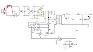
I think that the schematic you posted is only similar and not the one for the device as for a start the fuse value is different. The schematic shows a T2.5A and your board is a T1.6A
However, for a fuse to blow every time, you need to have a very low resistance path or a short circuit i.e. 0.00Ω between the two AC input leads i.e. the active and the neutral on pins 1 & 3 as shown in the image.
With the power disconnected from the device and the correct fuse inserted, place an Ohmmeter across pins 1 & 3 of the AC input connector on the board and check what the resistance measurement is.
If it measures a short circuit as you can see there are a lot of components connected directly between the two wires from the two red arrows to the 2 green arrows and none of them should be short circuit.
You will need to disconnect (unsolder) one side of each component that connects between the two wires, one at a time, until the short circuit disappears when testing between pins 1 & 3. Once it does then most likely you have found the faulty component.
Testing at board level with no obvious visual damage takes time and if the schematic is not the one you will have to trace the tracks on the board to find out which components are connected in the path
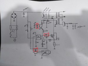
(click on image to enlarge)


2 Comments
Buen dia a todos. tengo el inconveniente que los componentes no se ven afectados, el partlante kilburn no enciende pero carga la bateria. revisando tengo continuidad en los capasitores c11, c37, c29, c26. en un principio crei que era el regulador de voltaje u7 pero este se encuentra dentro de la placa en corto, lo desolde y medi se encuentra en buen estado. y de igual forma reemplazandolo sigue el problema. quisiera saber si tienen alguna idea que me pueda ayudar
by Kristian Fonseca
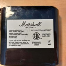
Li-ion battery from my Killburn says nominal voltage 14.8V
[image|3554145]
by Nikolay