I’m not sure if you still need help after all this time… I have checked the pictures and would have give some slightly different advice. I also don’t see any bridging that would cause the problem you stated as suggested previously, though you really do need to trim the excess wire after your done soldering. Think of the solder joints as volcanoes, or upside down cones where the walls of the cone have a concave (curved inward) appearance, and after trimming the freshly soldered joint, it would be a blown volcano with a flat top, or plateau about where the peak once was, even slightly below.
As for the wiring sequence itself, it’s: (Gnd)Ground, (RIn)Right in, (LIn)Left in, that’s for the left section. Then: (VO)Voltage Out, (VI)Voltage In, (Gnd)Ground, (LO)Left Out, (RO)Right Out, that’s for the right section.
I would say the code should be: Black, Red, White, and then: Green, Red, Black, Yellow, Yellow.
Essentially all of the second section, except for the voltage in, are outputs, so assuming black is ground, like usual, and red is voltage as usual, then green is voltage out , and both yellows are for signal out. I can’t tell from the picture if the yellow wires are exactly the same or if one is different (words, dotted lines, stripe, ridges, whatever) but if they are different, I’d say the plain yellow one is Right Out, and the marked yellow is left out. If they are the same, then it might not matter which is which. If that’s the case, you might try touching the wires to the pad to test and make sure which is which based on whether the appropriate speaker works, just do it with as low of volumes as possible so as not to damage anything.
As far as the switch is concerned… it seems to me that the wiring is done in a way that the voltage in is able to connect to output in either position, when normally it can only do so in one position. Honestly I’m really curious if the system was in fact working as it should other than the switch being on, or if you based your answer solely upon the light coming on. From the picture, it looks like you have the ground (out) hooked up to an input in section one (left) and in section two (right) you have voltage hooked up to an output while an output wire, the green, is hooked up to the only input (voltage). Essentially things are backwards and since everything that should be voltage is now an output and vise versa (more or less) the switch has two inputs instead of two outputs, or something similar. If I’m wrong about this then I can’t fathom why the labels are as they are.
I hope I helped, but just know that I’m not otherwise familiar with this system of yours, I’m just going off the information you’ve provided and that’s all. So take it slow and easy when attempting a change if you plan to do so. Good luck. If there’s anything I’m hesitant about, it’s whether the green and black ones should be swapped based on how I suggested. But they are both outputs, according to this schematic anyway, but voltage out would usually be labeled neutral (white or blue usually) and ground as earth ground (which is green usually, or bare). How old the system is may play a part in which is which, as well as where these wires lead to. But I don’t think it will cause any problems even if they’re switched. The other hesitancy is whether there are indeed two yellows in the second section or is one of them a shaded hard to make out white. From my perspective it looks like two yellows which is why I gave the answer I did. If that’s not the case it could change things so that the order would be: black (neu), yellow (hot), green (earth ground) red (right) and white (left). This would also account for the switch not turning off because the yellow would be the voltage in (hot) that was hooked up as either left or right out (output) and the black as an output instead of input, all this is supposing it didn’t work and you still need help. If you have a multimeter you can save the guess work, but I didn’t see anywhere if you did. If you don’t still need help…dismiss everything and have a nice time listening to your music. Lol.


1 Comment
I wanted to that you once more I was able to follow your color code and it worked :). But for some reason the on and off switch does not work it just stays permanently on was wondering I you had any idea why could that bee.
[image|1541710]
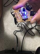
Switch On
[image|1541709]
Switch Off
[image|1541715]
I know is not the best sodering in the world firstime trying lol
by Anthony Gonzalez