Have a model 31C 707 type 0603 E1 that has broken 2 aluminum push rods. Why is one push rod steel and one aluminum? Can you replace the aluminum one with a steel one? And what is the proper valve setting ?
@mowerdumb not sure why this is done and not sure what you see (push rod vs. valve tappet?). It's best to not replace the aluminum one with a steel one. Something is going to give on your engine. Stick with what the B&S engineers designed. As for how to do the repairs etc. here is the manual from Briggs & Stratton. Based on the model number you've provided your engine is a OHV model 210000,280000 or 310000 Intek single cylinder. They are identical with the exception of the displacement.
All Models - Except Vertical Models 110000, 120000 Early Production
NOTE: Check valve clearance while the engine is cold.
1. Turn crankshaft counterclockwise until piston is at top dead center on the compression stroke. This prevents the compression release from holding the valves open.
2. Insert a narrow screwdriver or rod into the spark plug hole as a gauge, then slowly
turn crankshaft counterclockwise until the piston has moved down the bore by 1/4”
(6mm).
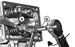
3. Using a feeler gauge (A, Figure 41), adjust rocker nut to obtain the clearance as listed in Section 12 - Engine Specifications.
4. Hold rocker nut and tighten the rocker ball setscrew (B) to the torque valve shown in Section 12 - Engine Specifications.
5. Check clearance again and re-adjust, if necessary.
6. Repeat for other valve.
NOTE: On some models, the nut and setscrew are positioned above the push rod ends.