Introduction
The G3 All-In-One was designed for the education market. It was clearly a fusion of the old beige computers and the upcoming iMacs. This transitional machine sported a 233Mhz or 266Mhz CPU, included three open PCI slots, and had a built-in 15" monitor. Hopefully this should help people who have acquired one of these small pieces of nostalgia.
What you need
-
-
You may want to have a table to work on the computer. It is pretty big.
-
Dimensions: width x height x depth
-
38cm x 51cm x 43cm
-
15in x 20in x 17in
-
-
-
Part A: Use a screw driver to remove the four screws in the back of the computer.
-
Part B: GENTLY, Pull out the tray half-way. The cables attached to the video/sound card can be damaged if you pull the tray out too far.
-
-
-
Two types of video/sound cards were installed in the AIO. There should be ribbon and video ports on both models.
-
Part A: Remove the ribbon cable from the top of the sound card. The label above this cable should say AIO.
-
Part B: Unlatch the clips from the black plug to remove the cable from the video/sound card. The label above the black plug should say AIO Video Card.
-
-
-
-
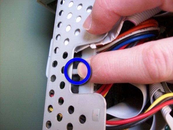
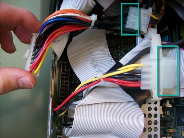
Part A: Use your index finger to pinch the clip on the main power plug while pulling it up from the motherboard.
-
Part B: Pull the 4-prong molex power plug apart.
-
-
-
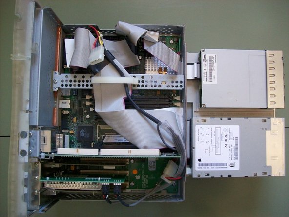
Part A: Apply pressure to the left and right tabs on the bottom of the motherboard tray to slide it out.
-
Part B: As you slide out the tray make sure the cable to the sound card doesn't get caught on the tray.
-
-
-
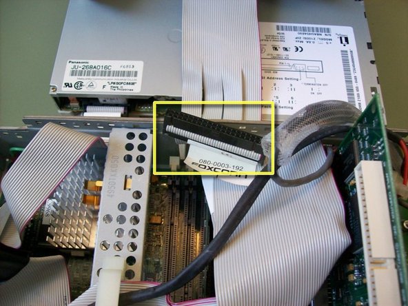
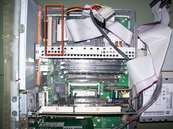
Part A: Open the clip on the center steel beam.
-
Part B: Disconnect the SCSI ribbon cable and IDE ribbon cable and set the cables aside.
-
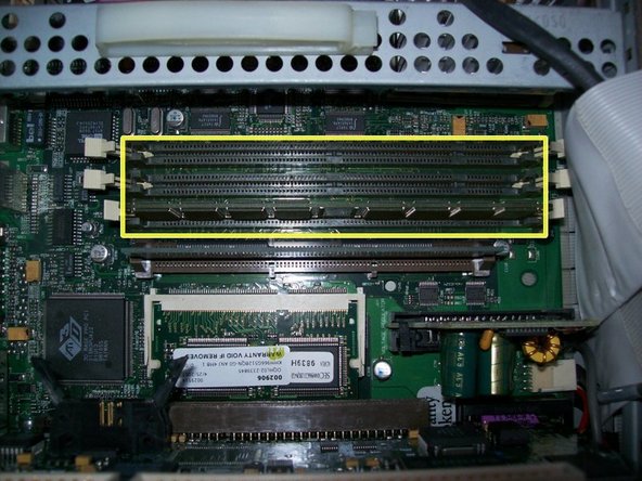
Part C: You should now be able to access the three RAM slots.
-
-
-
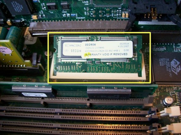
The VideoRAM/SGRAM slot is located between the video/sound card and the ROM slot.
-
Part A: Place the SGRAM in to the slot at an angle. Do not force the SGRAM in. If you are gentle the SGRAM will slide down into the slot and sit at an angle.
-
Part B: GENTLY Apply pressure to the corners of the SGRAM until it lies flat in the slot. The white slot has small clips that will "lock" the SGRAM in place. You may hear small clicks when the SGRAM is locked in place.
-


7 Comments
Specifications on my G3 All-In-One are:
Operating System: OS 9.2.2 and OS 10.1
Open Firmware Version: 2.0f1
CPU: Sonnet ZIF 500Mhz Upgrade
Hard Drive: 80GB <-3 Partitions
RAM: 256MB <-3.3v 100Mhz 168PIN SDRAM
SGRAM: 6MB
Video/Sound Card: Whisper Model#
Zip Drive: Functional
Floppy Drive: Functional
CDROM Drive: Functional
PCI slot 1-USB 1.1
PCI slot 2-ProTV
PCI slot 3-FireWire 400
First: OS 9.2.2 was installed on the 2nd partition of 2GB. This was so the CPU upgrade would install properly.
Second: OS 10.1 was installed on the 1st partition of 8GB in order for the upgrades and operating system to work properly.
The 3rd partition is storage
This computer was very picky when I tried to put RAM in it. Make sure you use the correct type.
Great Teardown!
What a strange machine. I unpacked and set up a computer lab of about 50 of them back in the day. The shape always reminded me of a tooth, for some reason.
Quote from Kyle Wiens:
What a strange machine. I unpacked and set up a computer lab of about 50 of them back in the day. The shape always reminded me of a tooth, for some reason.
Haha, it does look like a tooth. Great teardown!
Quote from Kyle Wiens:
What a strange machine. I unpacked and set up a computer lab of about 50 of them back in the day. The shape always reminded me of a tooth, for some reason.
The "Molar Mac" had that impression on a lot of people.
Thanks for the feedback guys.