Yellow Light of Death Repair

Featured Guide

Featured Guide

This guide has been found to be exceptionally cool by the iFixit staff.

Fix consoles plagued with the infamous "Yellow Light of Death".

  • Author: Brett Hartt
  • Time required: 1 hour
  • Difficulty: Difficult
  • Add Note x
  • x 555

Use this guide to repair PlayStation 3s with the "Yellow Light of Death" error.

Note: Your PlayStation may look slightly different inside. Be cautious when performing this process on your machine.

Sections (continued)
Relevant Parts
Image #1 Image #2

Add Note Edit Step 1 — Smart Plate  ¶ 

  • Use the tip of a spudger to remove the black rubber screw cover from the side of the PS3.

Image #1

Add Note Edit Step 2  ¶ 

  • Remove the single 8.5 mm T10 Security Torx screw from the smart plate.

Image #1 Image #2 Image #3

Add Note Edit Step 3  ¶ 

  • Pull the smart plate toward the hard drive bay, then lift it off the body of the PS3.

Image #1

Add Note Edit Step 4  ¶ 

  • Be sure to keep track of the small metal bracket loosely held in the top cover, if equipped.

Image #1

Add Note Edit Step 5 — Top Cover  ¶ 

  • Remove the following seven screws:

    • Six 52 mm Phillips screws

    • One 30 mm Phillips screw

Image #1

Add Note Edit Step 6  ¶ 

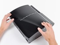
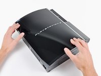
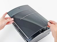
  • Lift the top cover from its rear edge and rotate it toward the front of the PS3.

  • Remove the top cover.
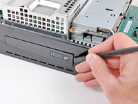
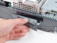
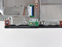
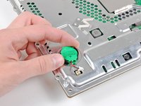
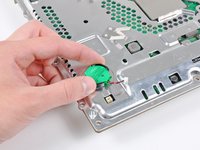
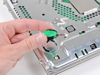
Image #1

Add Note Edit Step 7 — Blu-ray Disc Drive  ¶ 

  • Disconnect the Blu-ray power cable from the motherboard.

  • Pull the connector straight up and out of its socket.

Image #1

Add Note Edit Step 8  ¶ 

  • Lift the Blu-ray drive from the edge nearest the power supply and rotate it away from the chassis enough to access its ribbon cable.

Image #1 Image #2 Image #3

Add Note Edit Step 9  ¶ 

  • Use your fingernail to flip up the retaining flap on the Blu-ray ribbon cable socket.

  • Be sure you are prying up on the retaining flap, not the socket itself.

  • Pull the ribbon cable out of its socket.

  • Remove the Blu-ray drive from the PS3.

  • If replacing the Blu-ray drive, transfer the power cable to your new drive.

Image #1

Add Note Edit Step 10 — Motherboard Assembly  ¶ 

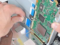
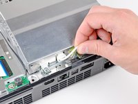
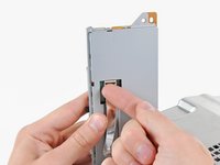
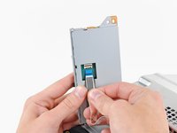
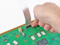
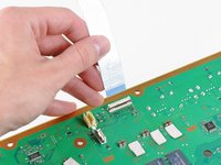
  • Pull the control board ribbon cable straight up and out of its socket on the motherboard.

Image #1 Image #2

Add Note Edit Step 11  ¶ 

  • Remove the two 12 mm Phillips screws securing the control board to the lower case.

  • Remove the control board and its attached cable from the PS3.

Image #1

Add Note Edit Step 12  ¶ 

  • Remove the following eight screws securing the motherboard assembly to the lower case:

    • Seven 12 mm Phillips screws (ph2)

    • One 30 mm Phillips screw

Image #1

Add Note Edit Step 13  ¶ 

  • Remove the control board bracket.

Image #1 Image #2

Add Note Edit Step 14  ¶ 

  • Use the flat end of a spudger to pry the hard drive bay cover away from the lower case.

  • Remove the hard drive bay cover.

Image #1

Add Note Edit Step 15  ¶ 

  • Lift the motherboard assembly out of the lower case.

Image #1

Add Note Edit Step 16 — AC Inlet  ¶ 

  • Remove the 7.7 mm Phillips screw securing the ground strap to the chassis.

Image #1 Image #2

Add Note Edit Step 17  ¶ 

  • Pull the AC-In cables slightly away from the rear cover for clearance to access the AC-In connector.

  • While depressing its locking mechanism, pull the AC-In connector out of its socket on the power supply.

Image #1

Add Note Edit Step 18  ¶ 

  • Pull the AC inlet out from the bottom of the rear cover, minding any of its cables that may get caught.

Image #1 Image #2

Add Note Edit Step 19 — Rear Cover  ¶ 

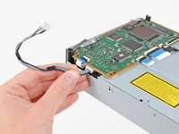
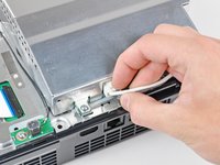
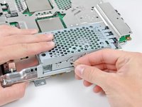
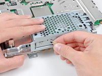
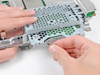
  • While lightly pulling the rear cover away from the logic board assembly, use the flat end of a spudger to release the clips along the top and bottom edges of the rear cover.

Image #1

Add Note Edit Step 20  ¶ 

  • Remove the rear cover from the logic board assembly.

Image #1 Image #2

Add Note Edit Step 21 — Heat Sink  ¶ 

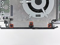
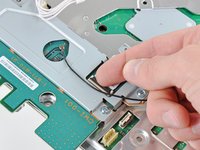
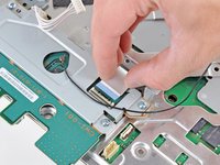
  • De-route the fan cables from the plastic finger molded into the heat sink.

  • Disconnect the fan from the motherboard.

  • Pull the connector straight up and out of its socket.

Image #1

Add Note Edit Step 22  ¶ 

  • Remove the two 9 mm Phillips screws securing the memory card reader to the chassis.

Image #1 Image #2

Add Note Edit Step 23  ¶ 

  • Lift the memory card reader out of the PS3 enough to access its ribbon cable.

  • Flip up the retaining flap on the memory card reader ribbon cable socket.

  • Be sure you are prying up on the retaining flap, not the socket itself.

  • Pull the ribbon cable out of its socket and remove the memory card reader.

Image #1

Add Note Edit Step 24  ¶ 

  • Disconnect the DC-In cables from the front of the heat sink.

  • Pull the connector toward the front of the PS3.

Image #1

Add Note Edit Step 25  ¶ 

  • Remove the five 9 mm Phillips screws securing the power supply to the chassis.

Image #1

Add Note Edit Step 26  ¶ 

  • Lift the power supply by its front edge to clear the two posts attached to the motherboard.

  • Remove the power supply.

Image #1

Add Note Edit Step 27  ¶ 

  • Remove the four 16.5 mm shouldered Phillips screws securing the heat sink to the motherboard.

  • Remove the two brackets held under the screws you just removed.

Image #1

Add Note Edit Step 28  ¶ 

  • Lift the motherboard assembly off the heat sink.

  • The heat sink may still be held in place by the thermal paste. If this is the case, gently pry the heat sink away from the motherboard housing. Make sure to not bend the copper piping on the heat sink.

  • Be sure to apply a new layer of thermal paste when reattaching the heat sink.

  • Never applied thermal paste before? Our thermal paste guide makes it easy.

Image #1 Image #2

Add Note Edit Step 29 — Motherboard  ¶ 

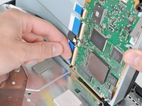
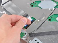
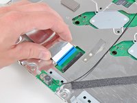
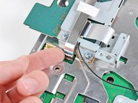
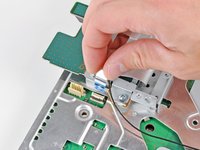
  • Flip up the retaining flap on the Blu-ray ribbon cable socket.

  • Be sure you are prying up on the retaining flap, not the socket itself.

  • Remove the Blu-ray ribbon cable.

Image #1 Image #2

Add Note Edit Step 30  ¶ 

  • Flip up the flap on the memory card reader ribbon cable socket and remove the ribbon cable.

Image #1 Image #2

Add Note Edit Step 31  ¶ 

  • Flip up the retaining flap on the Wi-Fi/Bluetooth ribbon cable socket.

  • Pull the Wi-Fi/Bluetooth ribbon cable out of its socket.

Image #1

Add Note Edit Step 32  ¶ 

  • Disconnect the DC-In cable from the motherboard and set it aside.

  • Pull the connector straight up and out of its socket on the motherboard.

Image #1

Add Note Edit Step 33  ¶ 

  • Disconnect the PRAM battery from the motherboard.

  • The PRAM socket is delicate and has the potential to break off the motherboard. If possible, hold down the socket as you disconnect the PRAM battery cable.

Image #1 Image #2 Image #3

Add Note Edit Step 34  ¶ 

  • Rotate the PRAM battery slightly counter-clockwise and remove it from the motherboard assembly.

Image #1

Add Note Edit Step 35  ¶ 

  • Remove the blue 8 mm Phillips screw securing the hard drive cage to the chassis.

Image #1 Image #2 Image #3

Add Note Edit Step 36  ¶ 

  • Push the hard drive cage toward the front of the motherboard assembly.

  • Remove the hard drive from the motherboard assembly.

Image #1

Add Note Edit Step 37  ¶ 

  • Remove the two 3.7 mm #0 Phillips screws securing the chassis to the hard drive socket.

Image #1

Add Note Edit Step 38  ¶ 

  • Remove the two 8.3 mm #0 Phillips screws securing the two halves of the motherboard together.

Image #1

Add Note Edit Step 39  ¶ 

  • Carefully feed the Wi-Fi/Bluetooth ribbon cable through the hole in the top motherboard cover.

  • Remove the top motherboard cover.

Image #1

Add Note Edit Step 40  ¶ 

  • Remove the motherboard from the bottom motherboard cover.

Image #1 Image #2

Add Note Edit Step 41  ¶ 

  • Flip up the retaining flap on the Wi-Fi/Bluetooth ribbon cable socket.

  • Remove the Wi-Fi/Bluetooth ribbon cable from the motherboard.

  • Motherboard remains.

Image #1 Image #2

Add Note Edit Step 42 — Yellow Light of Death (YLOD) Fix Kit  ¶ 

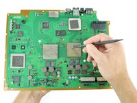
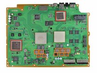
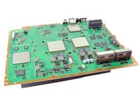
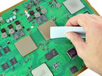
  • Using the flat end of the spudger, remove the old thermal paste off the CPU and GPU on the motherboard.

  • Using a cleaner such as Arctic Silver's ArctiClean or Goof-Off, clean the CPU and GPU.

  • In the same manner as previously described, remove the thermal paste from the heat sink.

Image #1 Image #2

Add Note Edit Step 43  ¶ 

  • Using your fingers or the flat end of a spudger, remove the old thermal pads on the logic board as indicated:

    • Large square thermal pads

    • Small Square thermal pads

    • Small rectangular thermal pads (located on the underside of the board, as highlighted in the second picture)

  • Some of the smaller thermal pads may be attached to the metal casing that surrounds the motherboard rather than the motherboard itself.

Image #1

Add Note Edit Step 44  ¶ 

  • Set the heat gun to "Low", and let it run for a few seconds to reach operating temperature.

  • Holding the motherboard upright, warm up the entire board with the heat gun. The board should be warm, but not too hot.

    • This will prevent damage to the board caused by localized thermal expansion.

Image #1 Image #2

Add Note Edit Step 45  ¶ 

  • Set the motherboard on a support so that the CPU and GPU are completely supported and level.

  • The support should be something that can resist temperatures upwards of 300 degrees Celsius. Suggestions: scrap lumber, old books, cardboard box.

  • In the next few steps, you will be reflowing the solder under the chips marked in red.

  • Once you begin reflowing the chips, do not touch or move the motherboard until it is completely cool. Doing so can render the motherboard irreparably damaged.

Image #1 Image #2

Add Note Edit Step 46  ¶ 

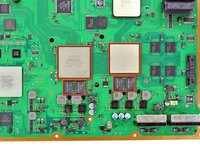
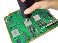
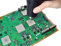
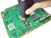
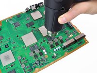
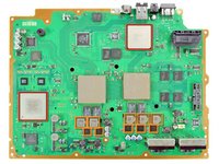
  • Using a circular motion, evenly heat (using low heat) each of the four areas for roughly 25 seconds each.

  • Begin heating the GPU, marked "RSX", and heat the chips in a zig-zag order.

Image #1 Image #2

Add Note Edit Step 47  ¶ 

  • Continue heating the chips using the same circular motion as described above, for about 25 seconds each.

Image #1 Image #2 Image #3

Add Note Edit Step 48  ¶ 

  • Ensure that the motherboard has completely cooled before continuing this guide.

    • If you have not applied thermal paste before you can check our thermal paste guide whilst it is cooling.

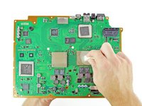
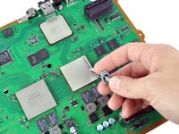
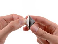
  • Apply a thin bead of thermal paste on the CPU.

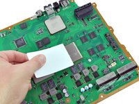
  • Using the thermal paste spreader card, spread the paste out thinly and evenly on the chip.

  • In the same way, apply a thin layer of thermal paste on the GPU.

  • Clean up any excess thermal paste off the motherboard.

Image #1 Image #2 Image #3

Add Note Edit Step 49  ¶ 

  • Peel the white plastic covers off one side of the new thermal pads. Be careful to just peel the cover off the pad, and not the transparent adhesive.

  • Apply the fresh thermal pads to the motherboard in the locations indicated:

    • Large square pads

    • Small square pads

    • Small Rectangular Pads

Image #1

Add Note Edit Step 50  ¶ 

  • Peel the remaining white plastic cover off the other side of thermal pads.

Related Products

Comments Add Note Comments are offturn on