
The Exposure Cycle
This section covers everything that happens from pushing the shutter button to the final 'thunk' of the mirror return. At a high level, the process looks like this.
- The shutter button releases the mirror, which flips up allowing the image to be projected onto the film plane.
- The mirror, reaching the 'taking' position, releases the opening curtain of the shutter.
- The opening curtain travels across the film gate beginning the exposure.
- After an appropriate amount of time, determined by either the high speed mechanism or the slow speed governor, the closing shutter curtain begins its travel, ending the exposure.
- The closing curtain reaches the end of its travel and triggers the mirror return.
- The mirror flips down into the 'viewing' position, allowing the user to see through the viewfinder again.
The camera uses this sequence (mirror releases shutter, then shutter returns mirror) so that the shutter can never open while the mirror is in the way. The following sections cover the process in greater detail, showing exactly which mechanisms are performing each action.
Mirror release
Shutter button


The shutter button houses a pin (red), which interacts with the shutter release plate (orange) inside the camera. The pin travels with the button during a normal press from the user. When a remote cable release is attached via the threaded connection, the pin travels independently from the button.
The pin will also rotate with the shutter lock. When locked, the semi-circular portion of the pin moves above a rigid section of the camera frame, preventing the button from being pushed.
Mirror release latch


A vertical shaft combined with a horizontal bar (red) transfers the button push to the mirror box mechanism. The bar contacts the mirror release latch (orange), moving it out of the way of the mirror release lever.
Mirror flip up


A large coil spring (red) powers the flip up mechanism. A series of levers transfers the power to the mirror lifting lever (orange), moving the mirror flat against the top of the mirror box. The image on the left shows the mechanism charged with the mirror in the viewing position. The image on the right shows the mechanism after the mirror has flipped up.
Aperture stop down

While the mechanism is lifting the mirror, it's also closing down the aperture in the lens to the set value. More specifically, it is releasing the aperture coupling lever (red), allowing the springs in the lens to close down the aperture.
Electrical contacts

When the mirror reaches the top of the mirror box, it closes the contact for the FP flash sync (red). See the section on Flash Sync for more details.
It also closes a contact (orange) that shuts off the light meter LEDs in the viewfinder, which helps prevent stray light leaks on the film.
Mirror box action
Here's a brief video of the mirror box mechanism performing all of the actions described above. It also shows how the mirror is charged and how it is released after an exposure.
Opening curtain release
Transport gear latch

As the shutter button pushes down the release plate mentioned earlier, it also depresses the transport gear latch (red). This decouples the top gear from the bottom gear and allows the top gear to spin freely as the opening curtain is traveling across the frame.
Opening curtain latch

When the mirror completes its travel to the top of the mirror box a lever will strike the opening curtain latch (red), releasing the opening curtain and beginning the exposure.
Both the opening curtain latch and the transport gear latch must be released for the opening curtain to start the exposure.
Opening curtain travel


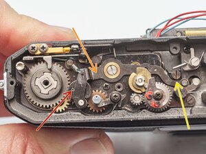
The opening wind gear (red) begins in the position shown on the left, makes almost one full counter-clockwise revolution, and ends in the position on the right. It's caught by the curtain break (orange), which prevents the curtain from bouncing off the end stop and back into the frame. If curtain bounce is detected, or if the wind gear is not reaching the end stop, the curtain break can be adjusted by turning the slotted screw (yellow), and changing the amount of engagement.
Curtain rollers


The force that pulls the shutter curtains across the frame is provided by the curtain rollers. The roller near the back of the camera (red) pulls the opening curtain, and the roller near the front of the camera (orange) pulls the closing curtain. Inside the rollers are torsional springs, which can be wound tighter or looser to control the speed of the curtains. The adjustment points (yellow) can be accessed on the bottom of the camera.
The travel time of the curtains in the Pentax MX is specified as 12.2-12.3 ms over a distance of 32 mm. The tension on the roller springs can be adjusted until both are within this range. After that, the engagement of the high speed cam can be tuned to meet the proper exposure times.
X flash sync

When the opening curtain reaches the end of its travel, a lever under the wind plate closes the X flash sync contact (red). See the section on Flash Sync for more details.
Closing curtain release
The delay of the closing curtain behind the opening curtain is determined by either the high speed mechanism or the slow speed governor, depending on what speed is selected. If the shutter speed is set to 1/60-1/1000, the high speed mechanism is used. If it is set to 1s-1/30, the slow speed governor is used.
High speed cam


As the opening curtain wind gear is spinning around, the high speed cam (red) turns with it. After some amount of rotation, the radius of the cam becomes large enough that it pushes out the closing curtain latch (orange), allowing the closing curtain to start its travel.
Selecting different speeds on the dial will put the high speed cam in different positions, resulting in different amounts of rotation before the closing curtain is released. Longer exposures require more rotation and shorter exposures require less. At 1/60, the opening curtain will travel the entire distance across the film gate before the closing curtain is released. At 1/1000, there are only a few millimeters between the edges of the two curtains.
Slow speed governor

For slow speeds, there is a second mechanism that delays the curtain. The slow speed governor is on the bottom of the camera and interacts with the closing curtain through a set of gears (red). The smaller pinion gear is attached to the bottom of the closing curtain shaft and spins as the curtain moves across the frame. The curtain starts its travel but runs into the governor plate (orange) before it can enter the film gate.
The slow speed governor uses a train of gears along with a couple additional features to slow down the closing curtain to various degrees. For the intermediate speeds, 1/30th to 1/15th of a second, simple inertia creates the required delay.
Slow speed escapement


If the governor needs to create a longer delay, it engages an escapement (red), which creates more resistance in the gear train. The image on right shows the governor set to a speed of 1s. The escapement is engaged for speeds up to 1/8th of a second
A feeler lever on a cam (orange) is used to engage or disengage the escapement. The cam is turned by the shutter speed dial on top of the camera.
Slow speed tuning


Lastly, the governor can change the amount of overlap between the governor plates. Less overlap means the closing curtain doesn't have to push it as far and can get by more quickly. This is how the governor achieves each of the individual speeds selectable by the user. The position of the governor plate is set by another feeler lever on a cam (red). If the speeds are inaccurate, the amount of overlap can be finely tuned using the eccentric adjustment (orange).
If a fast shutter speed is selected on the dial (1/60 - 1/1000), the governor plate is moved out of the way and doesn't interact with the closing curtain at all (yellow).
Closing curtain brake

The governor assembly has one more function unrelated to shutter timing, which is to brake the closing curtain. As the curtain reaches the end of its travel, the governor plate contacts a spring loaded arm (red). This slows down the curtain and prevents it from bouncing back into the frame and allowing unwanted exposure.
Mirror return


Underneath the closing curtain gear is a small stud (red). When the curtain reaches the end of its travel, the stud strikes a lever (orange). That lever, in turn, releases the mirror return latch (yellow) on the mirror box and a large spring (green) pulls the mirror back to the viewing position.
Winding the Camera
Three things happen simultaneously when the user actuates the advance lever of the camera.
- New, unexposed film is pulled out of the cannister and placed behind the shutter.
- Springs in the mirror mechanism are charged, making them ready to rapidly flip the mirror up into the 'taking' position.
- The shutter curtains are pulled back across the film plane to their starting positions.
The following sections describe in detail how each of the functions are achieved by the mechanisms in the camera.
Film transport
Advance lever drive


The advance lever is attached to a shaft (red) that passes through the frame counter assembly. The bottom of the shaft turns a set of ratcheting pawls (orange). The pawls allow the advance lever to turn the main wind gear in the counter-clockwise direction but also spring back to the stowed position with little force. The stud on the bottom of the ratchet gear (yellow) transfers the rotation to the top wind gear (green) and turns it during an advance.
Top wind gear


The top wind gear is connected to a shaft (red) that runs to the bottom of the camera and drives additional functions. It also has a ratcheting mechanism (orange), which prevents it from turning in reverse.
This is one of areas that saw changes over the production life of the MX. Some cameras have the ratcheting gear built onto the top wind gear (yellow) instead of under the frame counter.
Sprocket shaft


The bottom wind gear (red) drives several functions on the bottom of the camera. Related to film transport, it drives the sprocket shaft in the film chamber (orange), which provides the primary force for pulling film from the cannister.
The sprocket shaft has eight protrusions around the top and the bottom, which grab the holes on the edges of the film. During a frame advance, the shaft makes one complete revolution. An eight sprocket advance is standard for the 135 format and works out to 38 mm in length, 36 mm for the exposed image with a 2 mm spacing between frames.
Take-up spool


The wind gear also drives the take-up spool through an idler gear (red). The take-up spool is connected through a slipper clutch (orange) and cannot provide as much pulling force as the sprocket. As the take-up spool gathers more film, its effective diameter increases, and it doesn't need to rotate as much as the sprocket. The slipper clutch helps to equalize the tension in the system and allows for different rates of rotation. The slipper clutch also allows the take-up spool to spin during film rewind, while the sprocket has to be fully disengaged (see the section on film rewind for more details).
Mirror charging
Mirror charging lever

The mirror charging is also driven by the bottom wind gear. It turns a cam (red), which drives the long mirror charging lever (orange). The lever pushes a post (yellow) on the bottom of the mirror box towards the front of the camera. When the post is latched and held forward (green), the mirror mechanism is charged (see right).
Mirror springs

The lever on the mirror box charges two large springs. One spring is responsible for flipping the mirror up into the taking position (red) while the other returns it to the viewing position (orange). Both springs are shown in their charged positions in the picture.
The flip-up spring has a foam pad underneath, which is meant to dampen vibrations and quiet the spring when the shutter is fired. If the pad is worn out, the result is a subtle ringing sound after an exposure. It can be replaced with new foam or with a rubber sleeve, as is the case here.
Shutter charging
Transport gears

Shutter charging is handled on the top of the camera, with a mechanism located underneath the shutter speed dial. It begins with the top wind gear (red), which drives an idler gear and then the bottom transport gear (orange, hidden under the top gear). The top transport gear turns with the bottom transport gear when the camera is wound. When the shutter is fired, the top gear is temporarily disconnected, allowing it to move independently.
Wind gears

The top transport gear then drives the opening wind gear (red), which, in turn, drives the shaft of the opening shutter curtain (orange). The opening wind gear connects to the closing wind gear (underneath) through a stud on the underside, and they both turn together when the camera is wound. The closing wind gear connects to the closing curtain shaft (yellow) to control its movement.
When the shutter is wound, the wind gears are turned counter-clockwise, bringing the curtains back across the film plane. The curtains are slightly overlapped during winding to prevent light leaks on the film.
Latch points


When the shutter curtains reach their starting position, they are held in place with latches. The opening curtain latch (red) is located under the wind gear plate. It's not accessible without significant disassembly. The bottom transport gear is also latched (orange). The closing curtain latch (yellow) slides into place, but doesn't actually hold the curtain until an exposure is triggered.
Light Meter
The light meter in the Pentax MX is uncoupled, meaning that it only provides the user with information about the exposure, but it does not interact with the shutter or lens in any way. The batteries in the camera power the light meter, but are not required to make an exposure. If the batteries die or the electronics are not functional, the camera can still be used as normal. The light meter in the camera considers the following things when calculating exposure.
- Image brightness
- Selected aperture
- Selected shutter speed
- ISO Setting
Image brightness

There are two light sensitive silicone diodes (red) located on either side of the eye piece. The metering cells look at the image projected on the focusing screen and sense its brightness. The lenses for the metering cells are designed to make them more sensitive to brightness in the center of the scene, resulting in a 'center-weighted' reading.
Selected aperture


A ring behind the lens mount (red) couples with the aperture ring on the lens by a small tab. The ring is spring loaded and is pulled counter-clockwise when a lens is not attached. This reads as a very small aperture to the camera. When a lens is attached, the aperture sensing ring is pushed clockwise, towards larger apertures.
The position of the ring is communicated using a variable resistor. As the ring moves, feeler contacts slide along a resistive strip or a set of contacts (orange), depending on the production run. In either case, as the feeler contacts move, the resistance changes and the light meter interprets the different values as different aperture settings on the lens.
More specifically, the variable resistor is communicating the relative aperture value, as opposed to the absolute value. The metering cells are viewing an image that is projected through a wide open aperture, but the actual exposure will be through a smaller, stopped down aperture. In order to make the proper calculation, it needs to know the difference in stops between the aperture it is seeing through and the aperture that will be used for exposing the image. And that's what the resistor measures.
A good aperture resistor should range in value from 0.5 kOhm at the home position (smallest aperture) to the 9 kOhm when the lens is fully open with continuous readings in between. If it is significantly different or has dead spots, it can be disassembled and cleaned.
Selected shutter speed and ISO setting


The shutter speed is communicated in a similar manner. The dial is connected to a variable resistor inside the camera (red). Differences in position result in different resistance values, which the electronics use to calculate exposure.
While the ISO value is set independently, it connects to the same variable resistor as the shutter speed. So a setting of 1/60 at ISO 100 would yield the same resistance value as a setting of 1/250 at ISO 400.
Display in viewfinder

The light meter takes all of the inputs from the camera and determines whether the current settings would result in a well exposed image or one that is over/under exposed. The camera uses a scale of red, yellow and green LEDs in the viewfinder to communicate this to the user. If the exposure is appropriate, the green LED at the center of the scale is illuminated. If the settings would result in under exposure, the red or yellow LEDs on the bottom of the scale are illuminated. And since they are shown next to the slower shutter speeds in the viewfinder, they imply to the user that increasing the exposure time would improve results.
Power


The light meter does not operate continuously, but instead is turned on when the user presses the shutter button half-way down. The shutter release shaft then closes a contact (red) located on the bottom of the camera and turns on the meter. Additionally, if the advance lever is pulled out to its 'ready' position, the release shaft is held down (orange), keeping the contact closed. When the advance lever is pushed in, the shaft can fully return and the contact opens.
If the meter switch is not behaving correctly, the contact arms can be bent to achieve the proper gap. And the eccentric adjustment on the release plate can be tuned so that it interacts with the advance lever properly.
Meter Adjustment

The Pentax MX uses two variable resistors to adjust the light meter reading, VR B (red) and VR C (orange).
Viewfinder
The image enters the camera through the lens. Leaving the exit pupil, the image is upside down and backwards (flipped vertically and horizontally). The viewfinder takes that image and makes it comprehensible to the user, for purposes of both composition and focusing. It takes several components to achieve this.
Reflex mirror

The first is the mirror (red) directly behind the lens, which takes the image and reflects it upward onto the focusing screen. This corrects the vertical inversion of the image. On the focusing screen, the image can be seen right side up, but it is still inverted left-to-right.
Mirror angle


The mirror is set at exactly 45°, perfectly bisecting the right angle between the film plane and the focusing screen. This ensures that every light ray is traveling the same distance to reach the focusing screen. Light at the bottom of the image travels the same distance as light at the top of the image, which is critical for achieving uniform focus in the viewfinder. If the mirror is not at 45°, the top of the image could be in focus, but the bottom of the image would not (assuming the subject is flat).
Incorrect mirror angle can also affect image framing. If the mirror is too low (angle to the focusing screen is greater than 45°), the image in the viewfinder will be shifted up, cutting off the top of the frame.
If the mirror angle is out of spec, it can be adjusted. An eccentric on the inside of the mirror box (red) can be turned to move the mirror rest up or down.
Focusing screen


The focusing screen is positioned above the reflex mirror and below the prism. The image projected on the focusing screen is what the user actually sees when they look through the viewfinder of an SLR.
The focusing screen in the Pentax MX is easily removable and can be swapped for alternate screens with different features. Some have grids overlayed to help with composition while others have no split prism to avoid prism blackout with slower lenses. To remove it, pull the tab at the top of the mirror box (red) until the tray drops down. Carefully remove the focusing screen by the handling tab.
Fresnel lens

The bottom side of the focusing screen is a fresnel lens, which is essentially a collapsed convex or condensing lens. When examined up close, the surface of the lens looks like a series of tiny, concentric rings (red) and it serves to brighten the image for the user. From further away, the surface looks shiny with and shimmery effect.
Ground glass

The image is actually focused on the top surface of the focusing screen. Traditionally called a 'ground glass', the surface here is plastic, but it still has a matte finish to diffuse the light. The stock screen has an additional focusing aid in the center of the screen consisting of a single large split prism surrounded by a ring of micro-prisms.
Focus adjustment


To focus accurately, the optical distance to the film plane must exactly match the optical distance to the focusing screen. A plate (red) sits on top of the focusing screen, which controls the position of the top surface. There are four screws (orange) that set the height of this plate and, consequently, the focusing screen.
A camera technician would traditionally use a tool called an autocollimator to precisely set the position of the focusing screen. Alternatively, a home user can use a lens with a known accurate infinity stop to make the adjustment.
- Confirm that the mirror angle is correct before doing this adjustment.
- Mount the lens and set it to infinity.
- Choose a subject that is very far away (effectively infinity).
- Adjust the four screws until the subject is in focus.
Prism

The primary purpose of the prism is to correct the lateral inversion of the image, which is achieved using the angled roof. The image also undergoes two vertical inversions, but this results in a no net change once it has reached the eye piece.
The bottom surface of the prism in the Pentax MX is not flat like many cameras, but instead has a slightly convex surface (red). This serves as another condensing lens in the viewfinder's image chain and helps to focus more light on the eye piece.
Eye piece

When the user puts their eye to the viewfinder, the focusing screen is only a few centimeters away, optically. Too close to focus on without the aid of a lens. The eye piece (red) helps to focus the image on the retina so that it appears to be at infinity and is easier to view.
Exposure Settings
Both the selected aperture and shutter speed can be seen in the viewfinder so the user can be aware of the camera settings without having to remove the camera from their eye.
Aperture
The aperture number is displayed through what is effectively a window on the front of the prism. It looks down onto the aperture ring of the mounted lens with a field of view narrow enough to only show the selected f-number.
Shutter Speed


The shutter speed is shown on the right hand side of the viewfinder. The physical mechanism that displays the text (red) is located on the left hand side of the mirror box, and ends up on opposite side of the viewfinder after the prism laterally inverts the image.
The disc is connected to the shutter speed dial through a series of gears (orange) and a long thing cable that runs behind the mirror box (yellow). When the dial is turned, the cable is pulled, rotating the disc so that it displays the newly selected speed. The exact position of the text in the viewfinder can be fine tuned using the adjustment screws next to the mirror box (see Pentax MX Viewfinder Speed Indication Adjustment for more details).
Film Rewind


The film advance mechanism is only meant to go in one direction. In order to rewind the film, the sprocket shaft needs to be disengaged so it can spin backwards. The rewind button (red) is located on the bottom of the camera. When pushed, a lever (orange) moves into a slot under the button and holds it in place. The sprocket will then spin freely and stay disengaged while the film is being rewound.
The take-up spool does not need to be disengaged from the film advance mechanism. It is connected through a slipper clutch (yellow) and can spin backwards with just a little force.
Actuating the advance lever will push the holding lever out, pop up the rewind button and re-engage the sprocket shaft. Film should advance normally after that.
Flash Sync

The Pentax MX has two flash sync modes available; X (xenon) sync and FP (focal plane) sync. X sync is used when a flash is connected to the hot shoe (red) or the lower sync terminal (orange). FP sync is used when a flash is connected to the upper sync terminal (yellow). Modern flashes use xenon bulbs and operate in X sync mode but there may be some cases where a user prefers an older FP sync flash.
X sync


In X sync mode, the flash is triggered when the opening curtain reaches the end of its travel. Xenon flashes fire a burst of high intensity light for a very short period of time and it's designed to illuminate the entire frame of film all at once. Consequently, X sync can only be used for shutter speeds where the entire frame is exposed by the shutter for some length of time. On the MX, that is 1/60 and slower. At faster speeds, the shutter forms a slit that travels over the film, which would result in partial exposures with a xenon flash.
When the opening curtain reaches the end of its travel and the entire frame is exposed by the shutter, it closes a contact (red) under the wind plate. Check the continuity of the contact to troubleshoot flash sync issues. It should remain open until the curtain is completely across the frame, then it should close. Also check continuity at the sync terminal and the hot shoe contacts. The camera uses flexible connections (orange) rather than a soldered connection to fire a hot shoe flash. Check that the contacts are clean and properly shaped to make the connection when the top cover is installed.
FP sync

In FP sync mode, the flash is triggered when the mirror reaches the taking position, closing an electrical contact on the bottom of the mirror box. Older flashes used slower burning bulbs that were designed to illuminate the frame of film for a longer amount of time. The flash bulb should be at full brightness before the opening curtain starts to expose the film. These older flash bulbs can also be used at any shutter speed. Since they burn for a relatively long time, they will illuminate all parts of the frame as a high speed slit passes over the frame.
Self Timer
Winding


The self-timer is charged by rotating the lever on the front of the camera (red) counter-clockwise or away from the lens mount. On the backside of the front plate, a tab (orange) rotates a post (yellow) on the self-timer mechanism, winding the large main spring. A spring loaded arm (green) holds the escapement against the star wheel to keep the mechanism from unwinding.
Release

The self-timer is released by the small button above the lever on the front of the camera. This presses a lever at the top of the self-timer mechanism (red), which releases the escapement lock. As the main spring unwinds, it pushes down on a plate (orange), which in turn pushes down the horizontal shutter release arm (yellow). At the end of the unwinding, the release arm triggers the mirror release latch and begins the exposure cycle.
The screw in the middle (green) can be used to adjust the release point of the self-timer if it isn't triggering the mirror properly. The lower screw is a lock screw, which should be loosened first.
Depth of Field Preview


The depth of field preview is activated by pushing the lever on the front of the camera (red) clockwise or towards the lens mount. A lever on the backside of the front plate (orange) pushes a post on the mirror box (yellow). This lifts the aperture control lever on the mirror box, which releases the aperture tab on the lens. The aperture mechanism in the lens has its own spring, which closes the aperture blades down to match the value selected on the aperture ring. Releasing the depth of field preview lever returns the lens aperture to wide open.
1 Comment
This is the most useful piece of explanation I have seen about my favorite camera I have seen! Thank you from the bottom of my heart! Please continue with other articles on Pentax MX.
Nikolay Bakalov - Reply Share