What you need
-
-
Remove the SIM card and micro SD trays using a paperclip or SIM card remover to eject the trays.
-
-
-
The plastic frame is locked to the internals by a single screw located between the SIM and micro SD slots.
-
Remove the QR code sticker to reveal the screw.
-
Unscrew using a 0.7mm Hex screwdriver
-
-
-
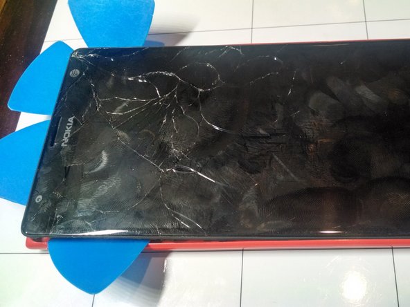
Using plastic picks, begin to separate the frame from the internals at the corner of the phone containing the SIM tray.
-
Work around the top of the device placing more picks between the frame and the internals.
-
Once the top is removed from the Plastic frame work down the sides and remove the plastic frame.
-
-
-
LIft up and remove the metal strap that covers the pop connector on the board.
-
-
-
-
Gently lift up on the four pop connectors to demate and remove them from the board.
-
-
-
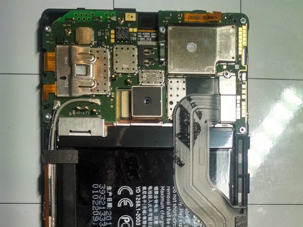
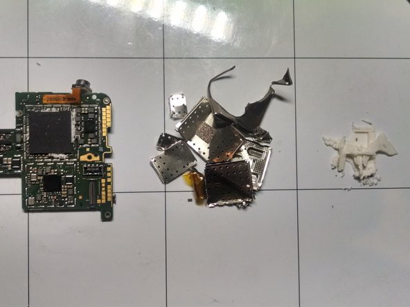
The board level shielding was soldered to the board and required prying and breaking to reveal the chips.
-
Once the board level shielding was removed, the silicone thermally conductive rubber was scraped away from the processor.
-
-
-
Samsung KLMAG2GEAC-B001 HMHB656EU 337
-
Samsung K3QF2F2ODM OGCE 6F63209X 337
-
405707 D925A4
-
RF7459A F14L10Y
-
SWH GMF81
-
WTR1605L OVV PPV438Z2 AB31801 10
-
-
-
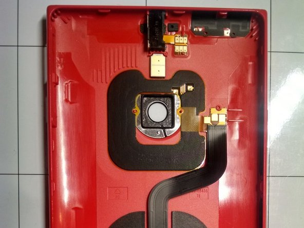
The antenna module is adhered to a daughter board with a soft sticky adhesive.
-
Remove the Antenna module by removing four T4 screws.
-
-
-
Remove the coaxial antenna cables by gently prying them up.
-
The Daughterboard and flex cable come out of the phone easily.
-
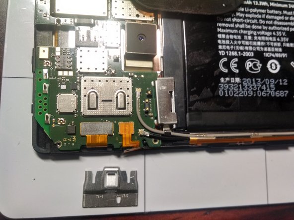
At this point we can see the USB connector is soldered to the board making replacement of this component expensive.
-
-
-
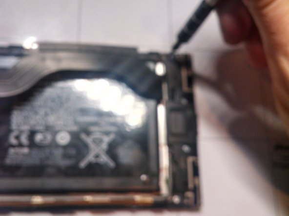
The battery is adhered quite strongly to the assembly.
-
A couple rounds of hot iOpener application followed by aggressive prying with plastic picks and metal tools was required to remove the battery.
-
-
-
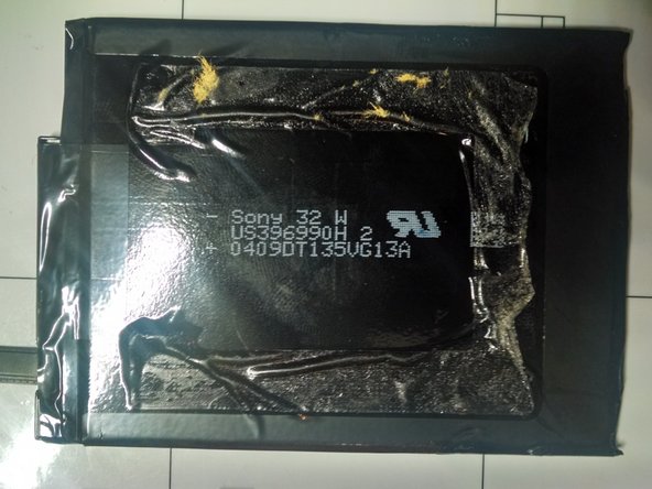
Views of The Battery and Bare Touchscreen Assembly
-