Introduction
The Mipro ACT-707S single channel diversity receiver is here! Here's the fillin' inside that metal box:
-EIA Standard ½ -rack unit size
- A color LCD panel
-FB-71 Rack Mount kit for 1 Half-rack ACT Receiver
-FBC-71 Rear-to-front Antenna kit for ACT Receivers
-ACT-707SD MIPRO PC-control Interface software
-AD-707 4-Channel Antenna Divider System
-AT-70+ Extension Antenna with Antenna Booster.
-AT-70B+MS-10 AT-90T Wideband Passive Directional Antenna
-AT-90R Wideband Active Directional Antenna
There are some key features for the wireless receiver:
-Channel ScanTM and ACTTM (Automatic Channel Targeting) are world first technology from MIPRO. One touch of Scan button quickly scans for an open, interference-free frequency. One touch of ACT button automatically uploads this frequency to the transmitter.
-It allows for the rapid change of channels, offers non-interfering channel selection and avoids spurious interference.
-EIA standard 1/2 –rack unit size
-World’s first color LCD panel.
-Full PC-control and monitoring of up to 64 channels simultaneously.
-Rugged and durable metal receiver housing.
-Dual “Pilo Tone & Noise Lock” protection circuitry prevents interference.
-Preset gain structure accurately set to equal the microphone capsule sensitivity.
-Switching power supply ensures stable power supply to the system.
-
-
Before we dive in blindly, let's look at the panel of the receiver:
-
For the front panel: Power Switch & Indicator: When switch is turned on, red indicator illuminates to denote normal power status.
-
Receiver Panel: Color LCD Panel.
-
For the rear panel: Rear Antenna B input Connector: B Antenna connector can be installed with antenna directly and provides power for antenna booster.
-
Rear Antenna A input Connector: A Antenna connector can be installed with antenna directly and provides power for antenna booster.
-
Balanced Audio Output Jack: With Cannon / XLR type connector provides balanced audio output signal from this jack to the amplifier.
-
Unbalanced Level Switch: "MIC" selection is for "Microphone-level" output. "LINE" selection is for "Line-out" level output.
-
DC Input Socket: The input socket for 12 Volt DC power. Please note that the polarity of the central pin in the socket is positive (+).
-
-
-
First, we take off the antenna from the receiver, which connected to the main body by the thread. By rotating the antenna, it can be taken off the main body very easily.
-
This screw moves the thread section from the outside cover to the main body.
-
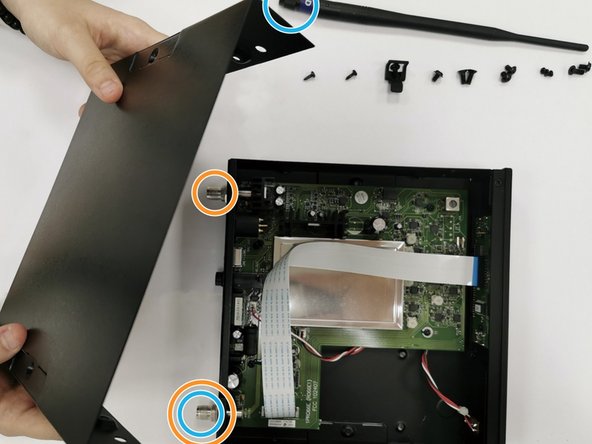
All the screws outside are loosen, to take the cover of the receiver off. It is a little bit difficult to take off the cover, because the cover are fixed to the box by both the screws and chamfers. It may be easier to take the cover off, if you open it from the corner.
-
The whole shell of the receiver, including the cover, is made of metal. It is sprayed into black and made by bending and welding. The shell has some holes on it to help fix the printed circuit board, the screen and the buttons.
-
The antenna is made of plastic and metal. The part to connect the receiver is made of metal and has threads inside, the rest of the antenna is made of plastic. The plastic shell protect the wires inside the antenna, and the space inside is too small to open.
-
-
-
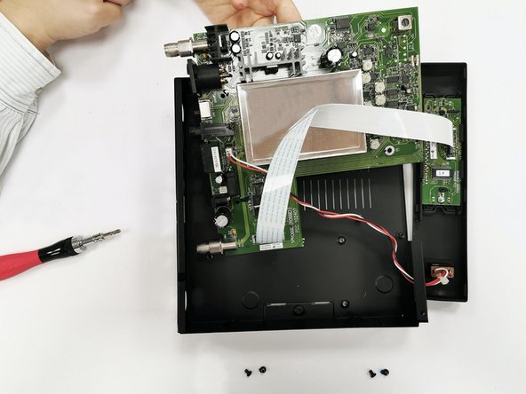
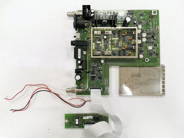
After taking off the metal cover, we can see the internal structure of the black box!
-
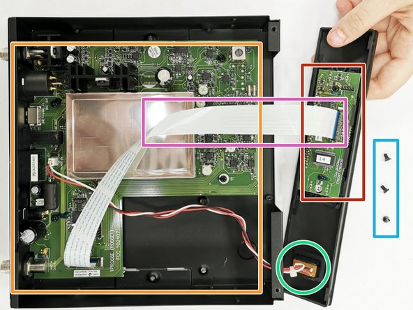
A large "L" shape printed circuit board is fixed to the bottom of the box by the nuts.
-
A small rectangular shape printed circuit board is fixed to the screen by the screws.
-
The two printed circuit board are connected by a flexible printed circuit.
-
The large printed circuit board is connected to the power button in the front of the receiver by three electric wires.
-
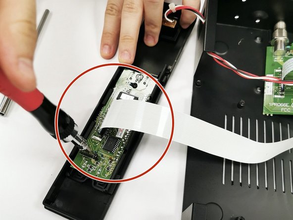
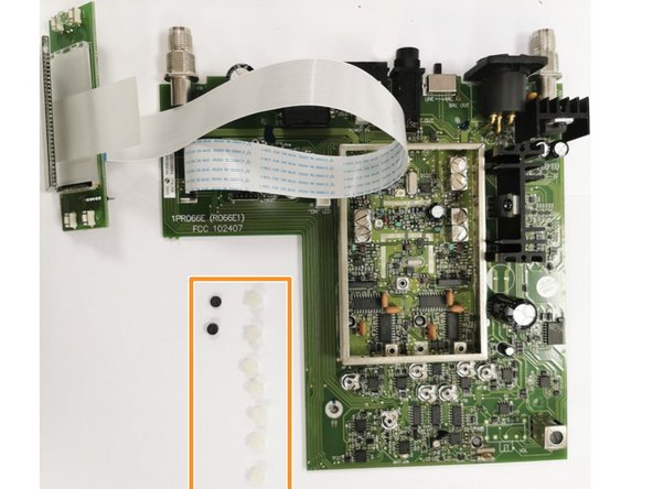
Take off the sideboard for the screen and buttons by loosening three screws from the outside.
-
The printed circuit board has copper wires inside and solder mask outside. All the patterns and components are welded on it. And the printed circuit boards have silk screen on them. 1PR066E(R066E1) FCC 102407 is on the large "L" shape printed circuit board. (R065B3)060603 1PR065B FCC is on the smaller printed circuit board.
-
-
-
-
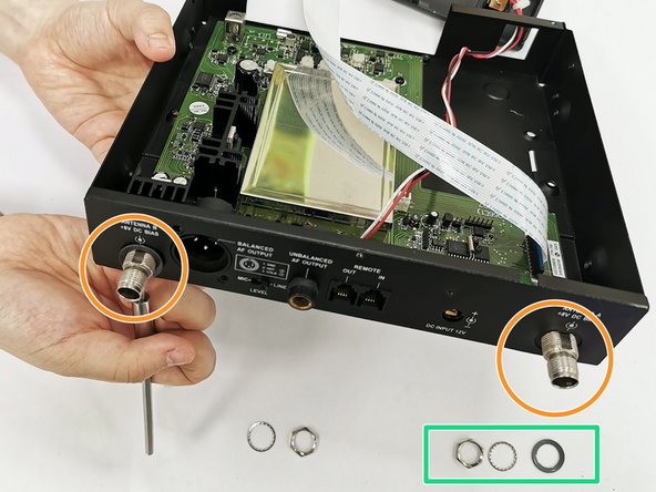
The large printed circuit board is fixed to the back side of the receiver by two screws.
-
Each screw has three different metal rings and one plastic ring (nuts).
-
The nuts are made by injection molding.
-
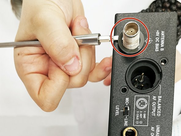
Take off the rings by using the slotted screwdriver.
-
Take the large printed circuit board out.
-
-
-
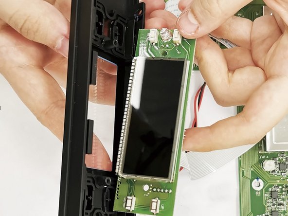
We use a screwdriver remove the front cover printed circuit board{(R065B3)060603 1PR065B FCC} with the display(LCD) and signal lights.(note: The screws connecting the circuit board and the front cover are very small, be careful not to damage the parts on the circuit board when disassembling)
-
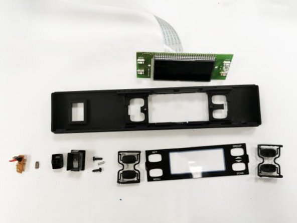
After disassembling, we got the front cover, display protective shell, LCD display, and 2X2 button shells, two Iron screws, and signal lights, two springs, one switch.
-
-
-
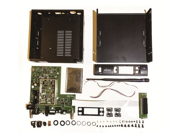
This is all the parts we disassembled.
-
We hope you enjoyed your 7-coure teardown meal. We found it very nutritious. This is a bit difficult for us to disassemble the machine for the first time.
-
Finally, let us introduce this Mipro ACT-707S from 2005 again.
-
It was one of the very advanced machines at the time. The word ACT means that the machine has an automatic channel lock function. The ACT series can be divided into LCD liquid crystal panels and VFD fluorescent panels.
-
The number 707 belongs to the LCD liquid crystal panel series, and 707S is a single-frequency pure automatic reception of LCD display. One of the deluxe versions of the device.
-