Introduction
The target user for the tool is a professional who uses a heat for forming and bending a variety of materials.
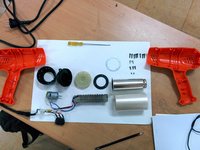
What you need
-
-
-
All screws on one side for ease of assembly
-
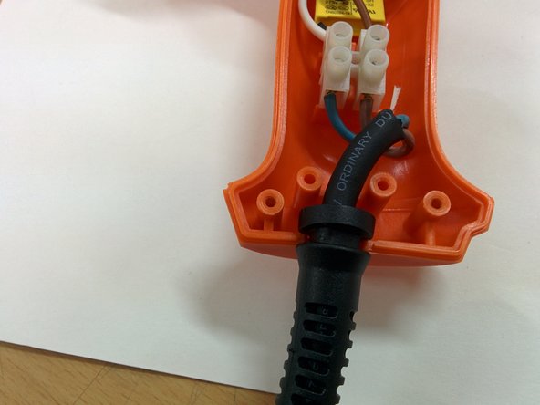
Wire has a stiffener for protection
-
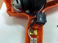
Switch is placed on handle in an ergonomic position so that one hand operation is easy
-
The back of the handle and the back of the body are in a straight plane in order to place the gun in vertical position after operation to cool it down
-
Vents are placed in the top part to facilitate air flow
-
The product is colored in industrial orange to be easily visible and distinguishable from the work environment
 Ask FixBot
-
-
-
All plastic detailing is made to have no overhangs
-
screwing details are used in order to locate the two half together without external jig
-
A lip joint is used in order to secure the assembly and also make it impermeable and rigid
-
-
-
-
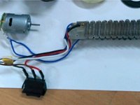
All electrical components are connected using connectors instead of direct soldering to facilitate easy replacement
-
The components have negative placers inbuilt in the in plastic injection mold
-
The electrical components are placed in order to prevent shorting
-
-
-
All heat components are suspended in order to prevent the heated elements to come in contact with plastic parts
-
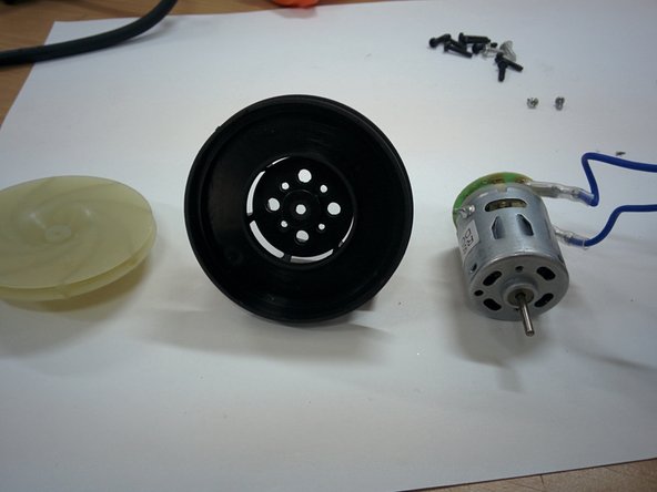
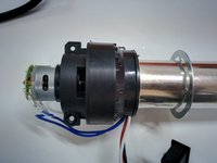
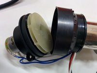
The blower chamber is designed in heat resistant pet in order to prevent it from deformation
-
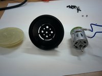
The motor and the blower fan has a press fit
-
-
-
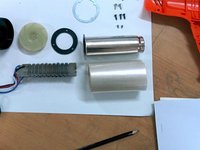
The heat tube is using mica support and kapton insulation
-
The external heat tube is stainless steel to prevent degradation of the tube.
-
The heat coil is used as a resistor to step down voltage for motor and hence it has a dual perpose
-
The heat coil is made of nichrome wire.
-
-
-
Minimum number of screws (variety) are used and all screws are self tapping in order to eliminate the use of nuts and loose parts.
-
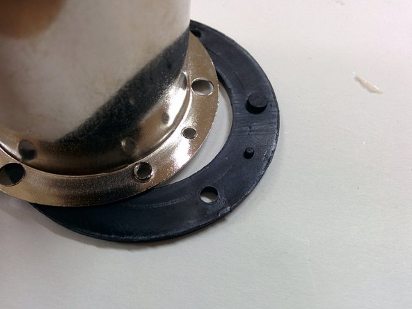
Assembly has location pins to align circular parts in a fixed orientation.
-
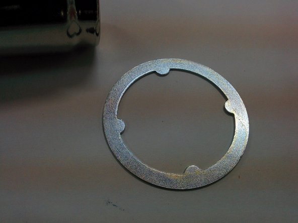
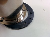
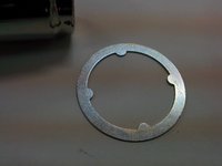
Heat rings are used in order to over heating
-
-








1 Guide Comment
Any idea where I can get a replacement for the plastic fan? It just fell off and melted and there doesn’t seem to be any information on the net. It’s a simple part. I’ve only used the gun a half a dozen times but it’s been years since it was purchased. Your instructions were helpful.
