Introduction
Lately, there's been much talk by the office water cooler about this all-in-one embedded device. It combines internet, LAN access via a Wi-Fi, and, oh yeah, it's also an alarm clock... It goes by the name of chumby one.
The chumby one is a completely open source platform, and the developers encourage all you hackers to dig right into the source code.
What follows is not for the faint of heart. You have been warned....
Check out the YouTube video slideshow of the teardown!
What you need
-
-
Welcome to another exciting edition of our popular teardown series.
-
Today's contender hails from the land of chumby industries, inc..
-
Measuring 4" wide x 4" tall x 3.5" deep, boasting an impressive 3.5" LCD color touchscreen, and a beefy 454 MHz ARM processor, it is our pleasure to welcome the chumby one to the grandest stage in all electronic dismemberment.
-
The chumby one combines all the greatness the internet has to offer. It integrates weather, news, music, videos, photos, social networking sites, and more with an extensive array of more than 1500 widgets in more than 30 categories.
-
That's all gravy and everything, but how's it look inside?
-
-
-
First use a thin metal spudger to remove the four self-adhesive plastic dots covering the screw holes.
-
Remove the four Phillips screws holding the cases together. You'll need a thin-shafted screwdriver to remove them.
-
Ventilation holes abound in the top and rear outer cases. Such a Swiss cheese case design allows the chumby to cool off without the need for a fan.
-
Pull the rear case away from the chumby to reveal the spiffy internals.
-
-
-
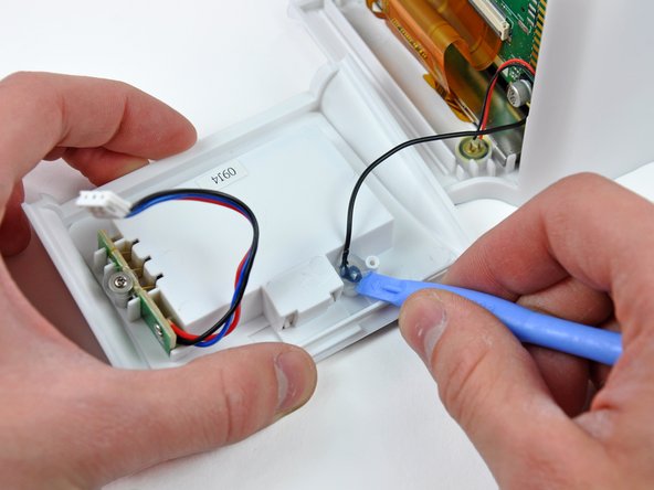
Slide the lower case away from the front of the chumby, then tilt it away from the logic board to reveal the battery connector. Taking as many precautions as possible, we decided to disconnect the battery connector from the logic board assembly.
-
Use a plastic opening tool to dislodge the plug of hot glue holding the FM antenna wire in the lower case. At this point you can de-route the FM antenna wire and remove the lower case from the chumby.
-
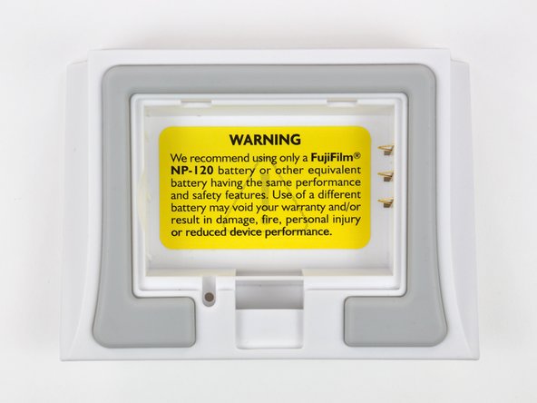
chumby industries, inc. recommends using only a Fujifilm NP-120 battery.
-
The NP-120 is a rechargeable Lithium-Ion camera battery. The chumby is equipped with circuitry to charge the battery when it is plugged into AC power.
-
-
-
-
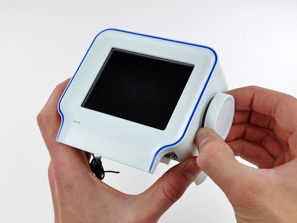
The volume knob is simply pressed onto the splined volume control shaft.
-
Use a plastic opening tool to pry evenly around the edge of the volume knob until you can remove it from the chumby.
-
Volume control commands are sent via a rotary encoder that translates angular degrees of rotation into binary code recognized by the board.
-
-
-
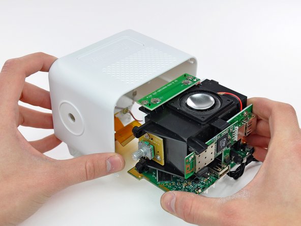
After removing four Phillips screws securing the inner chassis to the outer case, the guts can be removed in one piece.
-
Controls are routed through two daughterboards; one houses the two push-button elements and the other holds the volume dial.
-
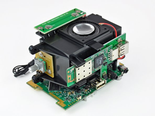
The wireless card is attached to a small interconnect board, converting the four-pin connector found on the logic board into the USB connector used by the wireless card.
-
After a bit too much wiggling, we broke the FM antenna lead where it attaches to the board. Soldering iron to the rescue!
-
-
-
Next, remove the four Phillips screws securing the display to the outer case.
-
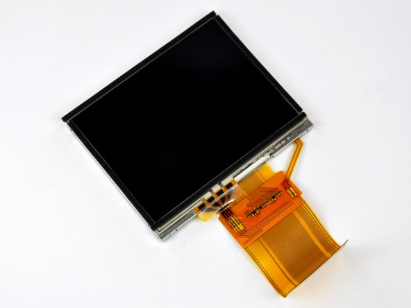
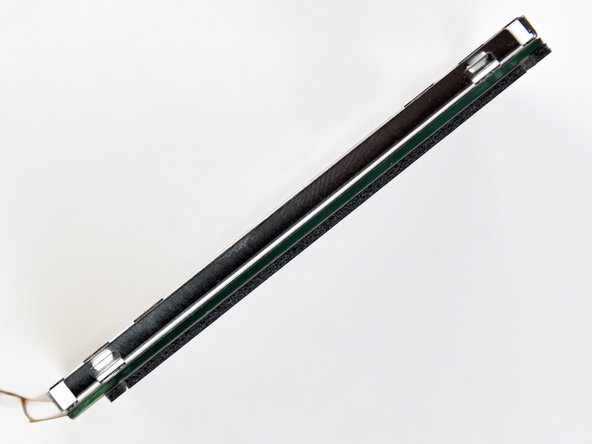
Lift the display and its metal shield out of the front case and bask in its 320x240 magnificence.
-
The display element is a 3.5", 320x240 pixel, 16 bits-per-pixel thin-film transistor (TFT) LCD.
-
The touchscreen element and the LCD both connect to the logic board through the same ribbon cable.
-
The outer edge of the glass touchscreen element is stuck to the outside of the LCD. It seems like dust and lint would have a hard time finding their way in between the two pieces.
-
As much as we love playing with sharp objects, we weren't brave enough to mix glass and exacto blades while trying to remove the touchscreen element.
-
-
-
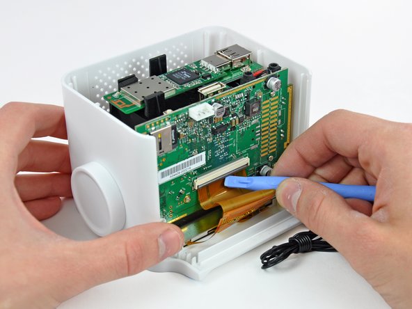
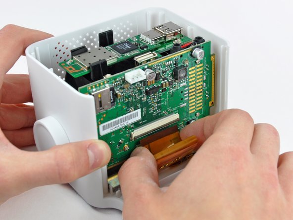
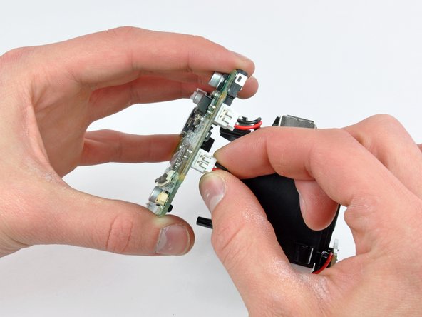
Carefully pull the logic board away from the inner chassis. As you pull the board away, be sure not to bend the pins on the Wi-Fi and volume knob interconnect boards.
-
After separating the two pieces slightly, disconnect the button panel and the speaker connectors from the logic board.
-
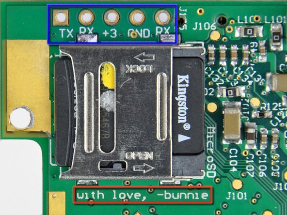
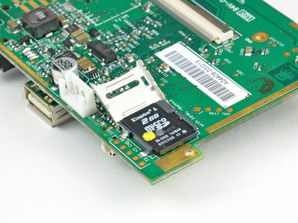
Hey look, a MicroSD card!
-
A row of sockets near the MicroSD socket provide connectivity for a TTL-level 115200, 8N1 serial console.
-
A message from the designer. How cute.
-
-
-
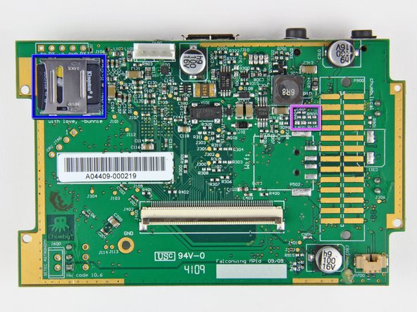
Some interesting features of the board include:
-
64 MB Hynix HY5DU121622BTP CMOS Double DataRate (DDR) Synchronous DRAM
-
GL8520G USB 2.0 Hub
-
MMA7455 3-axis accelerometer
-
QN8005B FM radio
-
Blank space for NAND flash (not used due to booting from MicroSD)
-
MicroSD socket complete with a 2GB Kingston MicroSD firmware card
-
Unpopulated passives for composite (NTSC/PAL) video output
-
-
-
Now, back to disassembling the chassis...
-
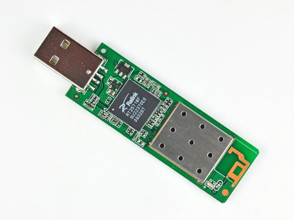
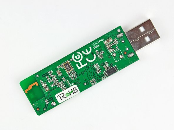
A simple tug removes the Ralink-based RT2571 USB Wi-Fi dongle.
-
The Ralink RT2571 supports both USB 1.1 & 2.0 for 802.11 a/b/g connectivity.
-
The chipset has the capability to operate in Windows XP, 2000, ME, 98SE, and in Linux.
-
Considering the open source nature of the chumby, wireless internet can conceivably be sacrificed for the extra USB port housing the Wi-Fi dongle.
-
-
-
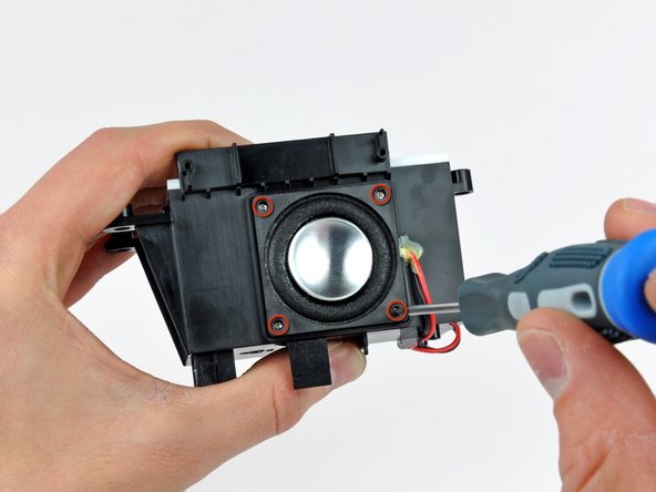
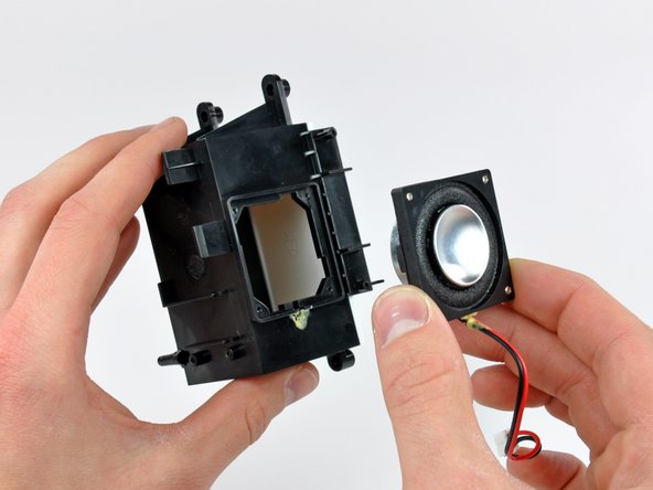
Get your groove on with the single 2W mono speaker mounted flush in the plastic chassis.
-
After removing the four Phillips screws securing the speaker to the chassis, use a sharp blade to carefully separate the speaker cables from the adhesive applied near the speaker opening.
-
The speaker wires are glued down to avoid any rattling noises from ruining your air guitar solo.
-
The speaker has a 7/8" concave aluminum diaphragm held to the frame with a foam rubber surround.
-
The white panel on the chassis is fitted with a conical port presumably to eliminate resonance.
-
-
-
Alas, we have reached the end of our endeavors. Good-bye chumby one, you will always be remembered as the one we tore apart...
-
Shameless plug: If your Apple product is suffering from any hardware-related ailments, use our site to fix it!
-


One Comment
Just saw this. *Very* nice work, and greatly appreciated. Still a chumby fan!