Free Shipping on Domestic Orders $75+

This translation was generated by a machine and has not been reviewed by a person yet. Speak this language? Review it.

why! N650DU Motherboard

What you need

    1. why! N650DU Motherboard, The Batteries: step 1, image 1 of 3 why! N650DU Motherboard, The Batteries: step 1, image 2 of 3 why! N650DU Motherboard, The Batteries: step 1, image 3 of 3
      • Unlock the button without spring.

      • Slide the battery up while unlocking the button with spring.

      Ask FixBot

      Add Comment

    1. why! N650DU Motherboard, Access to major components: step 2, image 1 of 3 why! N650DU Motherboard, Access to major components: step 2, image 2 of 3 why! N650DU Motherboard, Access to major components: step 2, image 3 of 3
      • Unscrew the two large screws circled in red.

      • Unscrew the two small screws circled in green.

      • Slide the plate down and lift it.

      Ask FixBot

      Add Comment

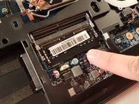
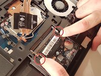
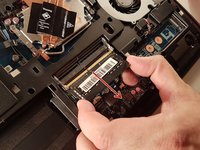
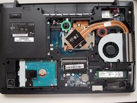
    1. why! N650DU Motherboard, RAM memory: step 3, image 1 of 3 why! N650DU Motherboard, RAM memory: step 3, image 2 of 3 why! N650DU Motherboard, RAM memory: step 3, image 3 of 3
      • Spread the two arms holding the RAM stick.

      • Remove the RAM stick.

      Ask FixBot

      Add Comment

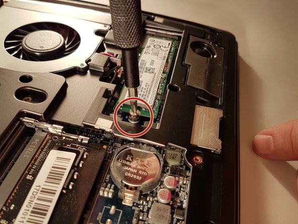
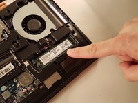
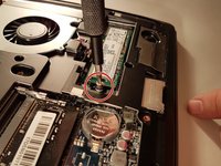
    1. why! N650DU Motherboard, SSD disk: step 4, image 1 of 2 why! N650DU Motherboard, SSD disk: step 4, image 2 of 2
      • Unscrew the screw circled in red.

      • Remove the SSD.

      Ask FixBot

      Add Comment

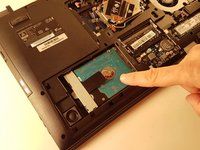
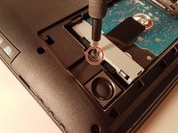
    1. why! N650DU Motherboard, Hard disk: step 5, image 1 of 3 why! N650DU Motherboard, Hard disk: step 5, image 2 of 3 why! N650DU Motherboard, Hard disk: step 5, image 3 of 3
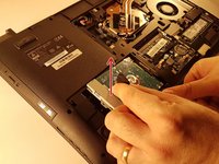
      • Unscrew the screw circled in red.

      • Pull the black tab up.

      Ask FixBot

      Add Comment

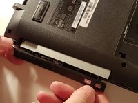
    1. why! N650DU Motherboard, CD / DVD RW drive: step 6, image 1 of 3 why! N650DU Motherboard, CD / DVD RW drive: step 6, image 2 of 3 why! N650DU Motherboard, CD / DVD RW drive: step 6, image 3 of 3
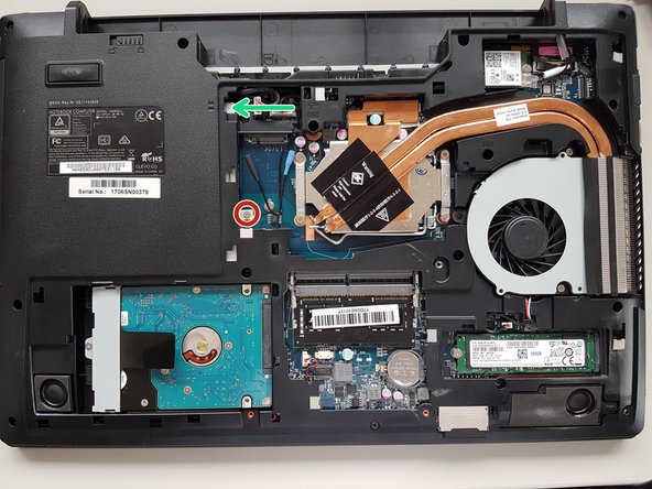
      • Unscrew the screw circled in red.

      • Push the drive to the location indicated by the green arrow.

      • Remove the drive from its location.

      Ask FixBot

      Add Comment

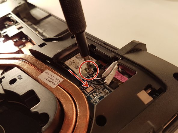
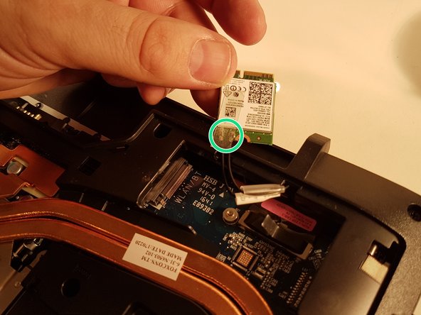
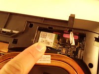
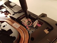
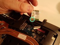
    1. why! N650DU Motherboard, Carte WLAN: step 7, image 1 of 3 why! N650DU Motherboard, Carte WLAN: step 7, image 2 of 3 why! N650DU Motherboard, Carte WLAN: step 7, image 3 of 3
      • Unscrew the screw circled in red.

      • Disconnect the WLAN card in the direction of the red arrow.

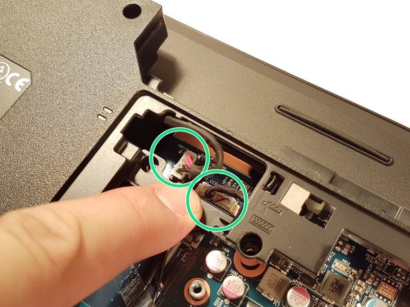
      • Unhook the two connectors circled in green on the WLAN card.

      Ask FixBot

      Add Comment

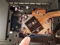
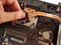
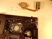
    1. why! N650DU Motherboard, Processor: step 8, image 1 of 3 why! N650DU Motherboard, Processor: step 8, image 2 of 3 why! N650DU Motherboard, Processor: step 8, image 3 of 3
      • Unscrew the four screws circled in red

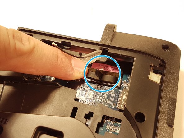
      • Lift the radiator with the black label

      Ask FixBot

      Add Comment

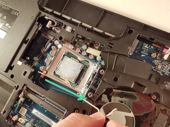
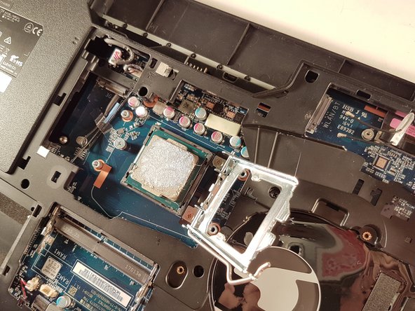
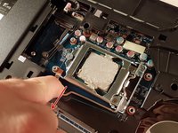
    2. why! N650DU Motherboard: step 9, image 1 of 3 why! N650DU Motherboard: step 9, image 2 of 3 why! N650DU Motherboard: step 9, image 3 of 3
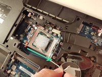
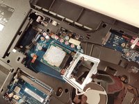
      • Push the lever in the direction of the red arrow while pushing it in

      • Lift the lever in the direction of the green arrow

      • Do not touch the bottom of the processor and take it by the sides

      Ask FixBot

      Add Comment

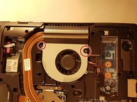
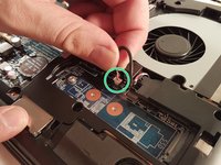
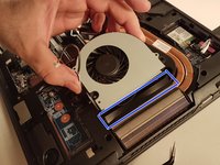
    1. why! N650DU Motherboard, The fan: step 10, image 1 of 3 why! N650DU Motherboard, The fan: step 10, image 2 of 3 why! N650DU Motherboard, The fan: step 10, image 3 of 3
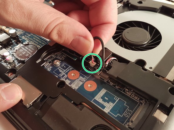
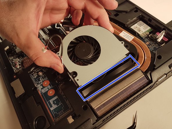
      • Unscrew the two screws circled in red.

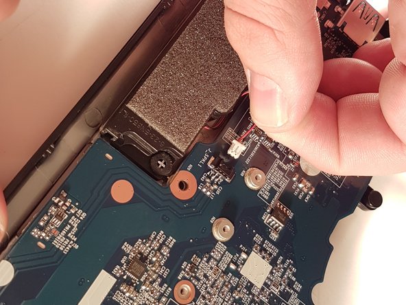
      • Disconnect the connector surrounded in green.

      • Remove the cooling fan by lifting the blue framed tab.

      Ask FixBot

      Add Comment

    1. why! N650DU Motherboard, Pile BIOS: step 11, image 1 of 2 why! N650DU Motherboard, Pile BIOS: step 11, image 2 of 2
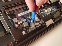
      • Remove the battery using a flathead screwdriver.

      Ask FixBot

      Add Comment

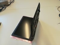
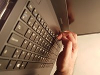
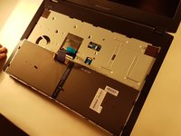
    1. why! N650DU Motherboard, The keyboard: step 12, image 1 of 3 why! N650DU Motherboard, The keyboard: step 12, image 2 of 3 why! N650DU Motherboard, The keyboard: step 12, image 3 of 3
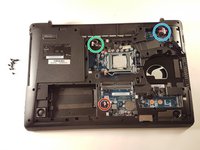
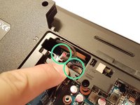
      • Unscrew the screws circled in red and green.

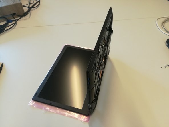
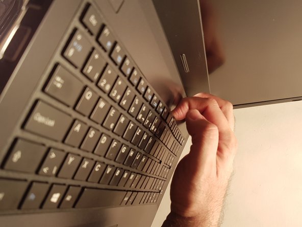
      • Put the computer in the position of the second image while pushing a paper clip into the hole of the screw circled in green until you hear a click.

      • Lift the keyboard.

      Ask FixBot

      Add Comment

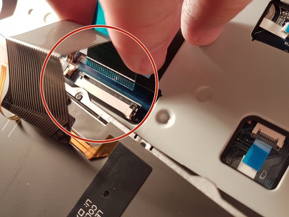
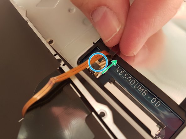
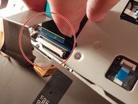
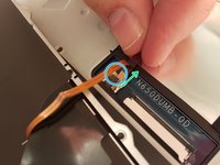
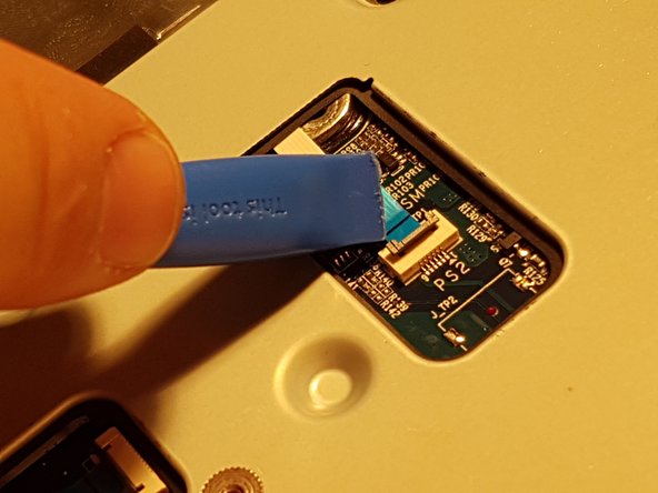
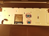
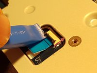
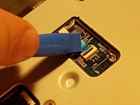
    2. why! N650DU Motherboard: step 13, image 1 of 3 why! N650DU Motherboard: step 13, image 2 of 3 why! N650DU Motherboard: step 13, image 3 of 3
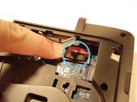
      • Remove the red circled connector.

      • Pull the white drawer that holds the connector circled in blue in the direction of the green arrow.

      • Remove the connector surrounded in blue.

      Ask FixBot

      Add Comment

    1. why! N650DU Motherboard, Motherboard: step 14, image 1 of 3 why! N650DU Motherboard, Motherboard: step 14, image 2 of 3 why! N650DU Motherboard, Motherboard: step 14, image 3 of 3
      • Lift the two black flaps.

      • Remove the two connectors circled in red.

      Ask FixBot

      Add Comment

    2. why! N650DU Motherboard: step 15, image 1 of 3 why! N650DU Motherboard: step 15, image 2 of 3 why! N650DU Motherboard: step 15, image 3 of 3
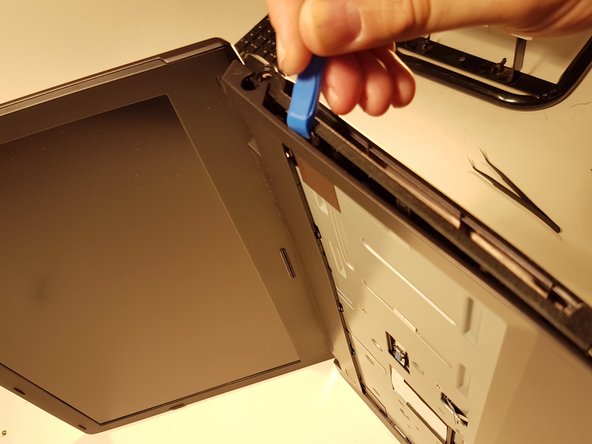
      • Remove the thirteen screws circled in red.

      • Remove the top cover.

      Ask FixBot

      Add Comment

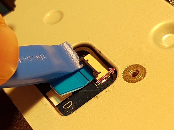
    3. why! N650DU Motherboard: step 16, image 1 of 3 why! N650DU Motherboard: step 16, image 2 of 3 why! N650DU Motherboard: step 16, image 3 of 3
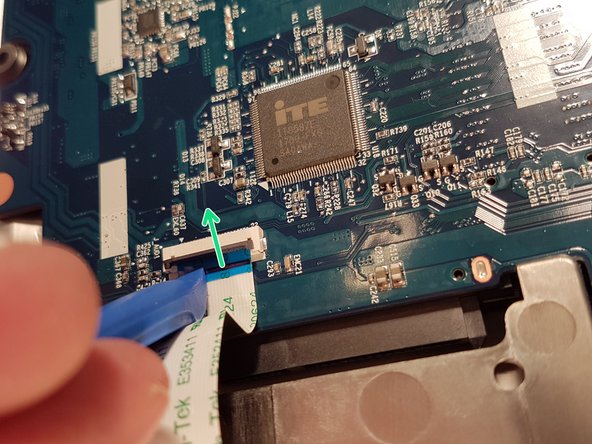
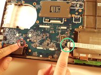
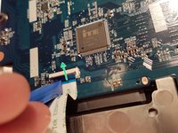
      • Lift the blue flap that holds the connector circled in green.

      • Disconnect the connector circled in green.

      • Disconnect the connector circled in red.

      Ask FixBot

      Add Comment

    4. why! N650DU Motherboard: step 17, image 1 of 3 why! N650DU Motherboard: step 17, image 2 of 3 why! N650DU Motherboard: step 17, image 3 of 3
      • Disconnect the two connectors located in the green zone.

      • Disconnect the connector surrounded in blue.

      • Disconnect the red circled connector.

      Ask FixBot

      Add Comment

    5. why! N650DU Motherboard: step 18, image 1 of 3 why! N650DU Motherboard: step 18, image 2 of 3 why! N650DU Motherboard: step 18, image 3 of 3
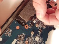
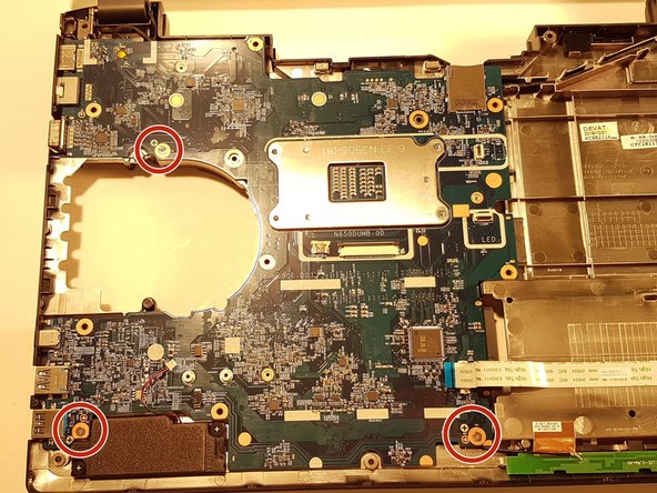
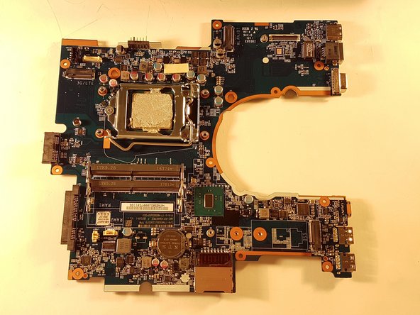
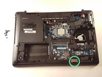
      • Remove the Micro SD port cover that is circled in green if there is one.

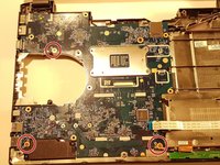
      • Unscrew the three screws circled in red.

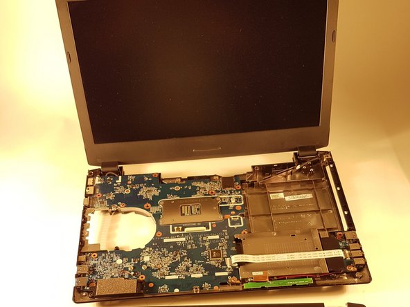
      • Carefully remove the motherboard.

      Ask FixBot

      Add Comment

Conclusion

To reassemble your device, follow the instructions in reverse order.

Cancel: I did not complete this guide.

One other person completed this guide.

Special thanks to these translators:

fr en

100%

irlanda is helping us fix the world! Want to contribute?
Start translating ›

Felice Suglia

Member since: 06/15/13

33,634 Reputation

283 Guides authored

0 Guide Comments

Add Comment

View Statistics:

Past 24 Hours: 2

Past 7 Days: 16

Past 30 Days: 97

All Time: 1,071