Free Shipping on Domestic Orders $75+

iVIEW-754TPC LCD Replacement

What you need

    1. iVIEW-754TPC LCD Replacement, Rear Panel: step 1, image 1 of 3 iVIEW-754TPC LCD Replacement, Rear Panel: step 1, image 2 of 3 iVIEW-754TPC LCD Replacement, Rear Panel: step 1, image 3 of 3
      • Before disassembling your tablet, make sure it is powered off.

      • Use plastic opening tool to release the clips holding the device together. The clips will take a small amount of pressure to release. Once you have the plastic opening tool inserted, use a twisting action to release the clips. Start from bottom of device and work all the way around.

      Ask FixBot

      Add Comment

    1. iVIEW-754TPC LCD Replacement, Remove Battery: step 2, image 1 of 3 iVIEW-754TPC LCD Replacement, Remove Battery: step 2, image 2 of 3 iVIEW-754TPC LCD Replacement, Remove Battery: step 2, image 3 of 3
      • Use flat side of the spudger to get under battery and use pressure to release from glue. Do this all the way around battery until it comes off.

      • At this point do not attempt to fully remove the battery as it is still attached to the logic board.

      Ask FixBot

      Add Comment

    1. iVIEW-754TPC LCD Replacement, Camera Assembly: step 3, image 1 of 3 iVIEW-754TPC LCD Replacement, Camera Assembly: step 3, image 2 of 3 iVIEW-754TPC LCD Replacement, Camera Assembly: step 3, image 3 of 3
      Tool used on this step:
      Tweezers
      $4.99
      Buy
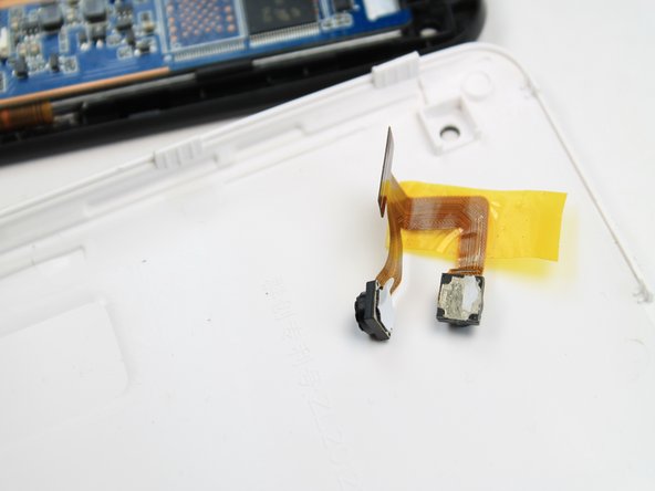
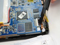
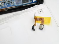
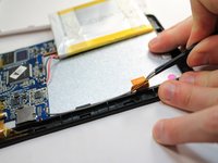
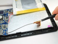
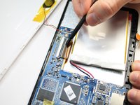
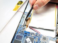
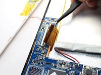
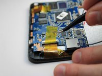
      • The camera module is located directly under the top right corner of the back cover.

      • Peel back the tape holding down the camera ribbon connector using a pair of tweezers.

      • As you peel the tape backward, the front facing camera may come out, this is not an issue.

      • If the front facing camera does not come out, gently lift it out with a pair of tweezers

      Ask FixBot

      Add Comment

    2. iVIEW-754TPC LCD Replacement, Remove Camera: step 4, image 1 of 2 iVIEW-754TPC LCD Replacement, Remove Camera: step 4, image 2 of 2
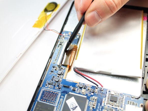
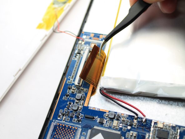
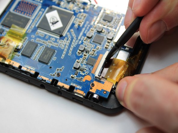
      • Use a spudger to lift flap on top of the camera ZIF adapter.

      • At this point the camera module can be easily removed with a pair of tweezers.

      • During reassembly, make sure you put the ZIF adapter snugly back into its socket and secure the flap.

      Ask FixBot

      Add Comment

    1. iVIEW-754TPC LCD Replacement, Logic Board: step 5, image 1 of 1
      • Remove the four 2.2mm Phillips screws holding the logic board in place. Place the screws on the iFixit magnetic project mat.

      Ask FixBot

      Add Comment

    2. iVIEW-754TPC LCD Replacement, WIFI Antenna: step 6, image 1 of 2 iVIEW-754TPC LCD Replacement, WIFI Antenna: step 6, image 2 of 2
      Tool used on this step:
      Tweezers
      $4.99
      Buy
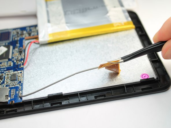
      • Gently peel the WIFI Antenna up using a pair of tweezers.

      Ask FixBot

      Add Comment

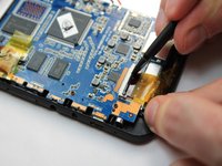
    3. iVIEW-754TPC LCD Replacement, Disconnect LCD: step 7, image 1 of 3 iVIEW-754TPC LCD Replacement, Disconnect LCD: step 7, image 2 of 3 iVIEW-754TPC LCD Replacement, Disconnect LCD: step 7, image 3 of 3
      • Use a spudger to lift the flap on top of the LCD ZIF socket.

      • Gently remove the ribbon cable from the socket using a tweezers.

      Ask FixBot

      Add Comment

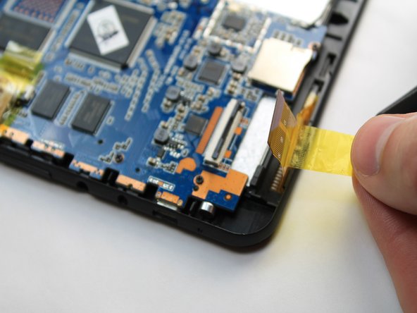
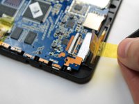
    4. iVIEW-754TPC LCD Replacement, Disconnect Digitizer: step 8, image 1 of 3 iVIEW-754TPC LCD Replacement, Disconnect Digitizer: step 8, image 2 of 3 iVIEW-754TPC LCD Replacement, Disconnect Digitizer: step 8, image 3 of 3
      • Use a spudger to lift the flap on top of the digitizer ZIF socket.

      • Gently pull the tape attached to the ribbon cable to remove the cable from its socket.

      Ask FixBot

      Add Comment

    5. iVIEW-754TPC LCD Replacement, Remove Logic Board: step 9, image 1 of 3 iVIEW-754TPC LCD Replacement, Remove Logic Board: step 9, image 2 of 3 iVIEW-754TPC LCD Replacement, Remove Logic Board: step 9, image 3 of 3
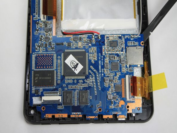
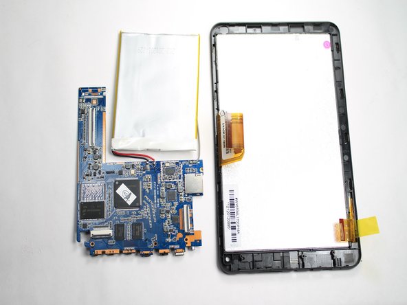
      • Gently slide the spudger below the logic board at the left side nearest the battery. Lift upward and away from the power button and bottom connectors.

      • The battery is still attached to the logic board. Be careful to not tear the two apart during removal.

      Ask FixBot

      Add Comment

    1. iVIEW-754TPC LCD Replacement, LCD: step 10, image 1 of 3 iVIEW-754TPC LCD Replacement, LCD: step 10, image 2 of 3 iVIEW-754TPC LCD Replacement, LCD: step 10, image 3 of 3
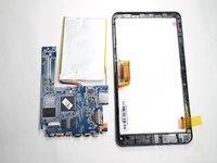
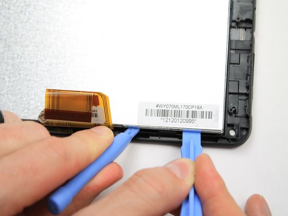
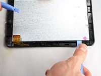
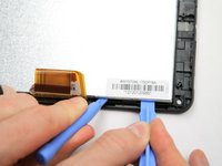
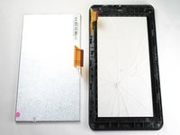
      • Insert a plastic opening tool between the LCD and digitizer on the side of the LCD with the ribbon cable. Use a second plastic opening tool to lift the LCD from the digitizer. Repeat this process on both sides of the LCD ribbon cable.

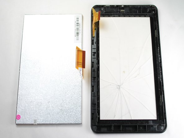
      • Fully remove the LCD from the digitizer.

      Ask FixBot

      Add Comment

Conclusion

To reassemble your device, follow these instructions in reverse order.

Cancel: I did not complete this guide.

2 other people completed this guide.

Robert Clark

Member since: 01/21/15

1,065 Reputation

7 Guides authored

Team

USF Tampa, Team 5-4, Brown Winter 2015 Member of USF Tampa, Team 5-4, Brown Winter 2015

USFT-BROWN-W15S5G4

4 Members

16 Guides authored

0 Guide Comments

Add Comment

View Statistics:

Past 24 Hours: 0

Past 7 Days: 5

Past 30 Days: 19

All Time: 1,023