Introduction
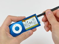
Replacing the logic board assembly gives you new flash memory as well as a new battery.
What you need
-
-
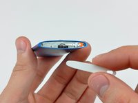
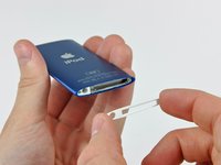
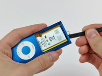
Insert the edge of an iPod opening tool into the gap between the outer case and the top bezel.
-
Pry the top bezel off the adhesive securing it to the display retainer.
-
-
-
-
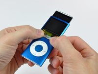
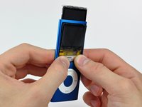
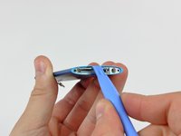
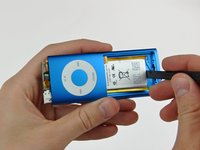
Use the edge of an iPod opening tool to separate the hold switch from the adhesive securing it to the top edge of the display.
-
-
-
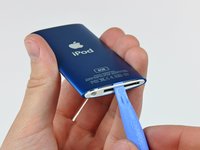
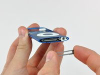
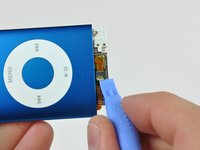
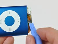
Insert an iPod opening tool between the bottom bezel and the dock connector.
-
Separate the bottom bezel from the adhesive securing it to the Nano and set it aside.
-


To reassemble your device, follow these instructions in reverse order.
Cancel: I did not complete this guide.
37 other people completed this guide.

7 Guide Comments
Wouldn't it be easier to open the ZIF socket whilst it is still stuck down?
On step 11 I found that the cable was still stuck down by the bit under the metal case. The opening tool failed to get at this.
I cut the live head off a match and trimmed it to a long chisel edge.
Pine is soft,strong and non conductive.I was able to poke under the metal body and release the remaining adhesive seal.
Failure. Another broken iPod due to the incompleteness of step 20. I will add a step 21 with description but I will need some nice looking pictures.
Mine broke because of accidentally pulling the board out too fast, but it's dead anyways.
TOOLS: I don't see any offset legs in the screws themselves, however either my 00 phillips is bigger than yours, or these screws are actually 000 phillips. In either case, I found that the heads were full of adhesive, and using a tiny flathead driver and a sharp knife I was able to clear it out just enough to get the screws out.