Introduction
Connects the iPhone to a computer or charger via iPhone cable.
What you need
Video Overview
-
-
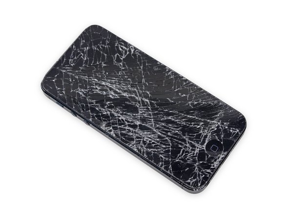
If your display glass is cracked, keep further breakage contained and prevent bodily harm during your repair by taping the glass.
-
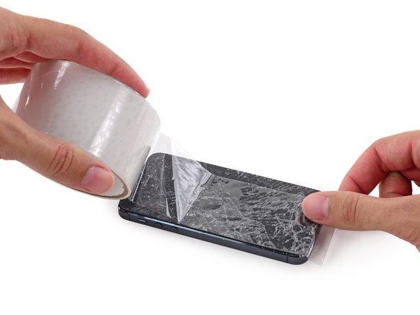
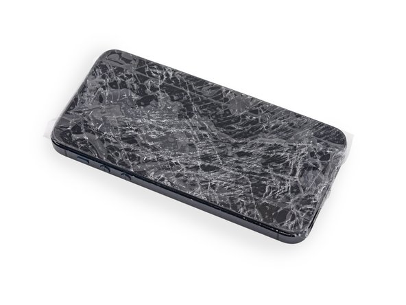
Lay overlapping strips of clear packing tape over the iPhone's display until the whole face is covered.
-
-
-
Remove the metal handle from the suction cup. It's easier and safer to grip the suction cup's base instead of the metal handle.
-
Use a small suction cup near the Home button to gently pull up the bottom portion of the iPhone's display assembly.
-
-
-
Continue to hold the display assembly with one hand, and use your other hand and a spudger to disconnect the black ribbon cable labeled "1."
-
Start from the ribbon and work your way towards the outside edge of the case.
-
-
-
Rotate the display assembly up until it is roughly vertical. This will allow easier access for disconnecting the remaining cables.
-
Use a spudger to disconnect the black ribbon cable labeled "2."
-
-
-
-
Use a spudger to flip up the white plastic tab holding the remaining ribbon cable in place. The white tab will rotate up 90 degrees, releasing the ribbon cable.
-
Slide the black ribbon cable out of its connector, and remove the display assembly from the iPhone.
-
-
-
Insert your SIM eject tool or a paper clip into the hole next to the headphone jack.
-
Press down on the tool until the SIM card tray pops out.
-
Grasp the SIM card tray and slide it out of the iPhone.
-
-
-
Remove the following 8 screws:
-
Five 2.3 mm Phillips #00 screws with partial threads securing the logic board to the rear panel.
-
Two 2.3 mm Phillips #00 screws with full threads securing the logic board and camera.
-
One 2.9 mm Phillips #00 screw from beneath the "Do not remove" sticker.
-
-
-
Use a spudger to gently remove the camera retaining clip, (formerly secured by the removed screw) and gently pry the camera up and out of its housing in the rear panel. The camera cannot be removed entirely yet because it's connected to the bottom of the logic board.
-
-
-
Remove the following 3 screws:
-
Two 1.5 mm Phillips #00 screws, one on either side of the dock connector.
-
One 2.4 mm Phillips #00 screw near the ribbon cable labeled "4."
-