Introduction
The motherboard includes all ports except the DC-In board.
What you need
-
-
Use a coin to rotate the battery locking screw 90 degrees clockwise.
-
Lift the battery out of the computer.
-
-
-
Pull the keyboard release tabs (shown in yellow) toward you and lift up on the keyboard until it pops free.
-
If the keyboard does not come free, use a small flathead screwdriver to turn the keyboard locking screw (shown in orange) 180 degrees in either direction and try again.
-
Flip the keyboard over, away from the screen, and rest it face-down on the trackpad area.
-
-
-
Close the display and flip the computer over.
-
Remove the three hex screws using a T8 Torx screwdriver.
-
-
-
-
Remove the following 10 screws from the bottom shield:
-
Six 3 mm Phillips
-
Three 7.5 mm Phillips
-
One 14 mm Phillips
-
-
-
Remove the following 11 screws from the bottom of the computer:
-
Three 3 mm Phillips around the battery compartment.
-
Three 4.5 mm Phillips along the optical drive bezel. (a magnetic screwdriver may help to lift these screws out)
-
One 12 mm Phillips in the lower right corner.
-
Four 14.5 mm Phillips.
-
-
-
Remove the following 16 screws:
-
Thirteen 3 mm Phillips.
-
One 3 mm Phillips.
-
Two 4 mm Phillips.
-
-
-
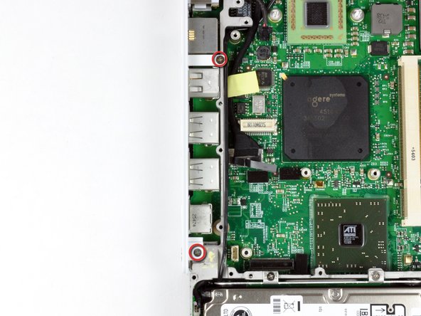
Remove the two Phillips screws at the corners of the modem.
-
Remove the two Phillips screws at the corners of the modem.
-
-
-
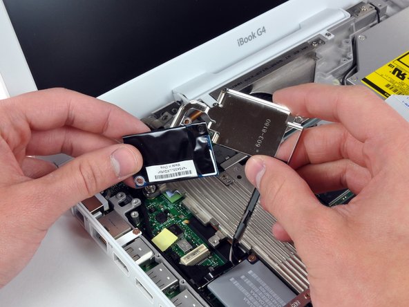
Remove the three 3 mm Phillips screws securing the AirPort card bracket to the metal framework.
-
Lift the AirPort card retaining bracket up and out of the computer.
-
-
-
Remove the following 9 screws and 2 nuts from the heat sink:
-
Four 3 mm Phillips from around the fan and the heat sink bracket. The bracket can also be removed at this point.
-
One 11.5 mm (left) and one 4.5 mm (right) Phillips from the plastic fingers of the hinge grill.
-
One 4.5 mm Phillips at the top right corner of the heat sink.
-
Two 6 mm Phillips on the lower left corner and face of the heat sink.
-
Two 4 mm screw nuts with attached springs from either side of the heat sink.
-
-
-
Remove the two Phillips screws securing the white plastic fingers of the I/O bezel to the metal framework.
-


To reassemble your device, follow these instructions in reverse order.
To reassemble your device, follow these instructions in reverse order.
Cancel: I did not complete this guide.
20 other people completed this guide.
