Introduction
Use this guide to repair PlayStation 3s with the "Yellow Light of Death" error.
Note: Your PlayStation may look slightly different inside. Be cautious when performing this process on your machine.
What you need
Video Overview
-
-
Use the tip of a spudger to remove the black rubber screw cover from the side of the PS3.
-
-
-
Remove the following seven screws:
-
Six 52 mm Phillips screws
-
One 30 mm Phillips screw
-
-
-
Lift the top cover from its rear edge and rotate it toward the front of the PS3.
-
Remove the top cover.
-
There is a plastic hook located in a hole on the top back right hand side corner. Carefully push the plastic hook a bit from the rear of the machine with a spudger to release the rear right of the casing.
-
-
-
Lift the Blu-ray drive from the edge nearest the power supply and rotate it away from the chassis enough to access its ribbon cable.
-
-
-
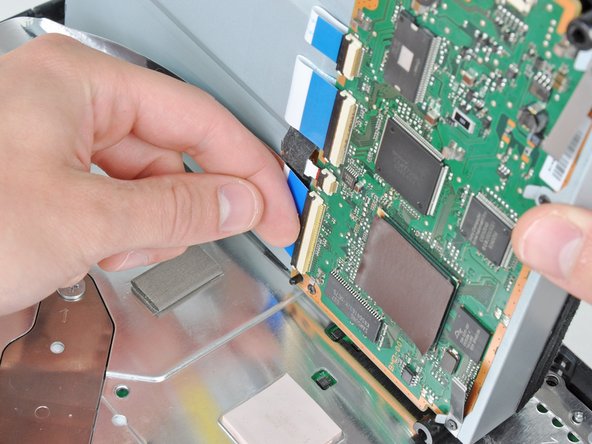
Use your fingernail to flip up the retaining flap on the Blu-ray ribbon cable socket.
-
Pull the ribbon cable out of its socket.
-
Remove the Blu-ray drive from the PS3.
-
-
-
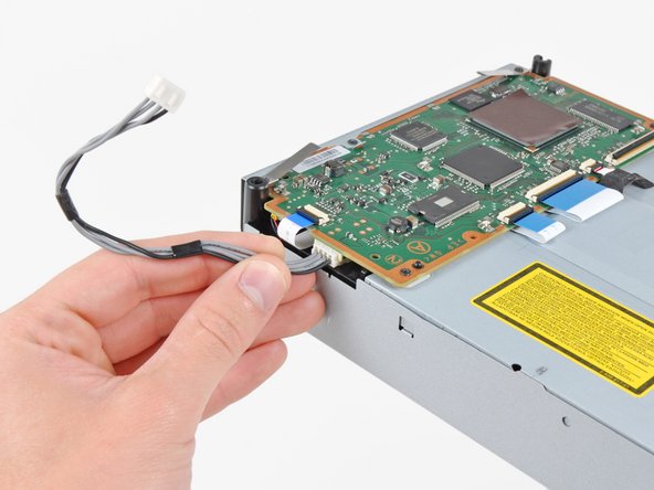
Pull the control board ribbon cable straight up and out of its socket on the motherboard.
-
-
-
Remove the two 12 mm Phillips screws securing the control board to the lower case.
-
Remove the control board and its attached cable from the PS3.
-
-
-
Remove the following eight screws securing the motherboard assembly to the lower case:
-
Seven 12 mm Phillips screws (ph2)
-
One 30 mm Phillips screw
-
-
-
Use the flat end of a spudger to pry the hard drive bay cover away from the lower case.
-
Remove the hard drive bay cover.
-
-
-
Pull the AC-In cables slightly away from the rear cover for clearance to access the AC-In connector.
-
While depressing its locking mechanism, pull the AC-In connector out of its socket on the power supply.
-
-
-
-
Pull the AC inlet out from the bottom of the rear cover, minding any of its cables that may get caught.
-
-
-
While lightly pulling the rear cover away from the logic board assembly, use the flat end of a spudger to release the clips along the top and bottom edges of the rear cover.
-
-
-
De-route the fan cables from the plastic finger molded into the heat sink.
-
Disconnect the fan from the motherboard.
-
-
-
Lift the memory card reader out of the PS3 enough to access its ribbon cable.
-
Flip up the retaining flap on the memory card reader ribbon cable socket.
-
Pull the ribbon cable out of its socket and remove the memory card reader.
-
-
-
Lift the power supply by its front edge to clear the two posts attached to the motherboard.
-
Remove the power supply.
-
-
-
Remove the four 16.5 mm shouldered Phillips screws securing the heat sink to the motherboard.
-
Remove the two brackets held under the screws you just removed.
-
-
-
Lift the motherboard assembly off the heat sink.
-
Be sure to apply a new layer of thermal paste when reattaching the heat sink.
-
-
-
Flip up the retaining flap on the Blu-ray ribbon cable socket.
-
Remove the Blu-ray ribbon cable.
-
-
-
Flip up the retaining flap on the Wi-Fi/Bluetooth ribbon cable socket.
-
Pull the Wi-Fi/Bluetooth ribbon cable out of its socket.
-
-
-
Rotate the PRAM battery slightly counter-clockwise and remove it from the motherboard assembly.
-
-
-
Push the hard drive cage toward the front of the motherboard assembly.
-
Remove the hard drive from the motherboard assembly.
-
-
-
Remove the two 8.3 mm #0 Phillips screws securing the two halves of the motherboard together.
-
-
-
Carefully feed the Wi-Fi/Bluetooth ribbon cable through the hole in the top motherboard cover.
-
Remove the top motherboard cover.
-
-
-
Flip up the retaining flap on the Wi-Fi/Bluetooth ribbon cable socket.
-
Remove the Wi-Fi/Bluetooth ribbon cable from the motherboard.
-
Motherboard remains.
-
-
-
Using the flat end of the spudger, remove the old thermal paste off the CPU and GPU on the motherboard.
-
Using a cleaner such as Arctic Silver's ArctiClean or high alcohol content rubbing alcohol, clean the CPU and GPU.
-
-
-
Using your fingers or the flat end of a spudger, remove the old thermal pads on the logic board as indicated:
-
Large square thermal pads
-
Small square thermal pads
-
Small rectangular thermal pads (located on the underside of the board, as highlighted in the second picture)
-
-
-
Set the heat gun to "Low", and let it run for a few seconds to reach operating temperature.
-
Holding the motherboard upright, warm up the entire board with the heat gun. The board should be warm, but not too hot.
-
-
-
Set the motherboard on a support so that the CPU and GPU are completely supported and level.
-
-
-
Using a circular motion, evenly heat (using low heat) each of the four areas for roughly 25 seconds each.
-
Begin heating the GPU, marked "RSX", and heat the chips in a zig-zag order.
-
-
-
Continue heating the chips using the same circular motion as described above, for about 25 seconds each.
-
-
-
If you have not applied thermal paste before you can check our thermal paste guide whilst it is cooling.
-
Apply a thin bead of thermal paste on the CPU.
-
Using the thermal paste spreader card, spread the paste out thinly and evenly on the chip.
-
In the same way, apply a thin layer of thermal paste on the GPU.
-
Clean up any excess thermal paste off the motherboard.
-
-
-
Apply the fresh thermal pads to the motherboard in the locations indicated:
-
Large square pads
-
Small square pads
-
Small Rectangular Pads
-
Two 3cm x 3cm Squares
-
Ten 1cm x 1cm Squares
-
Five 1.5cm x 0.5cm rectangles
-